


735
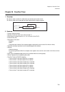
Chapter 35 Free-Run Timer
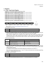
4.Registers
4. Registers
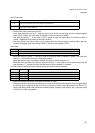
4.1 TCCS: Timer Control Register
A register for controlling the operation of the free-run timer.
• TCCS0 (free-run timer 0): Address 01F3h (access: Byte, Half-word, Word)
• TCCS1 (free-run timer 1): Address 01F7h (access: Byte, Half-word, Word)
• TCCS2 (free-run timer 2): Address 01FBh (access: Byte, Half-word, Word)
• TCCS3 (free-run timer 3): Address 01FFh (access: Byte, Half-word, Word)
• TCCS4 (free-run timer 4): Address 02F3h (access: Byte, Half-word, Word)
• TCCS5 (free-run timer 5): Address 02F7h (access: Byte, Half-word, Word)
• TCCS6 (free-run timer 6): Address 02FBh (access: Byte, Half-word, Word)
• TCCS7 (free-run timer 7): Address 02FFh (access: Byte, Half-word, Word)
(About attributes, see “Meaning of Bit Attribute Symbols (Page No.10)”.)
• bit7: Select the count clock
• When you change the setting of the count clock selection bit, do so when other peripheral modules (the
output compare, input capture, etc.) using the output of the free-run timer are stopped.
• When using the external clock, the period of the external clock must be more than double of the
peripheral clock (CLKP). When using the output compare, in order to allow the compare-match output
and interrupt generation, the external clock input of at least 1 clock is required after the compare-match.
• bit6: Interrupt request flag
• When the count value of the free-run timer overflows, or the clear mode bit (MODE) is “1”, the interrupt
request flag is set to “1” if the count values of the free-run timer and the compare register (OCCP) match
and the counter is cleared.
• To enable the interrupt request, the interrupt enabling bit must be set to do so (IVFE=“1”).
• When the interrupt request flag is set to “1”, and “0” is written at the same time, the interrupt request flag
is set to “1”. (Setting the flag has priority.)
• bit5: Enable interrupt requests
• When the interrupt request enabling bit is set to “1”, the interrupt request (IVF) is enabled.
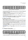
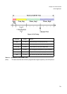
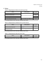
7 6 543210 bit
ECLK IVF IVFE STOP MODE CLR CLK1 CLK0
0 0 0 0 0 0 0 0 Initial value
R/W R (RM1), W R/W R/W R/W R/W R/W R/W Attribute
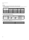
ECLK Select the count clock
0 Internal clock (the peripheral clock divided by n)
1 External clock (CK pin)
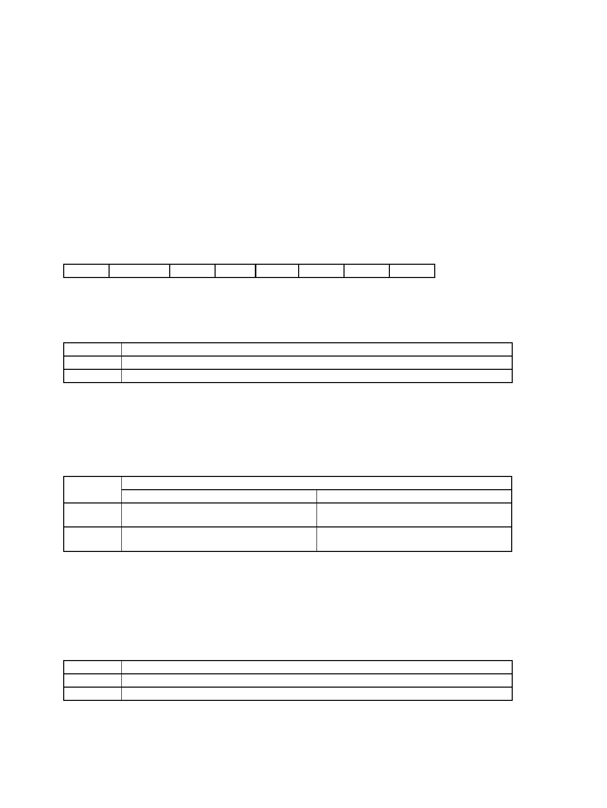
IVF
Status
Read Write
0 No interrupt request present Clear the flag (IVF).
1
Interrupt request present
(Overflow or compare-match)
No effect on operation
IVFE Operation
0 Disable interrupts
1 Enable interrupts