747
Chapter 36 Input Capture
1.Overview
Chapter 36 Input Capture
1. Overview
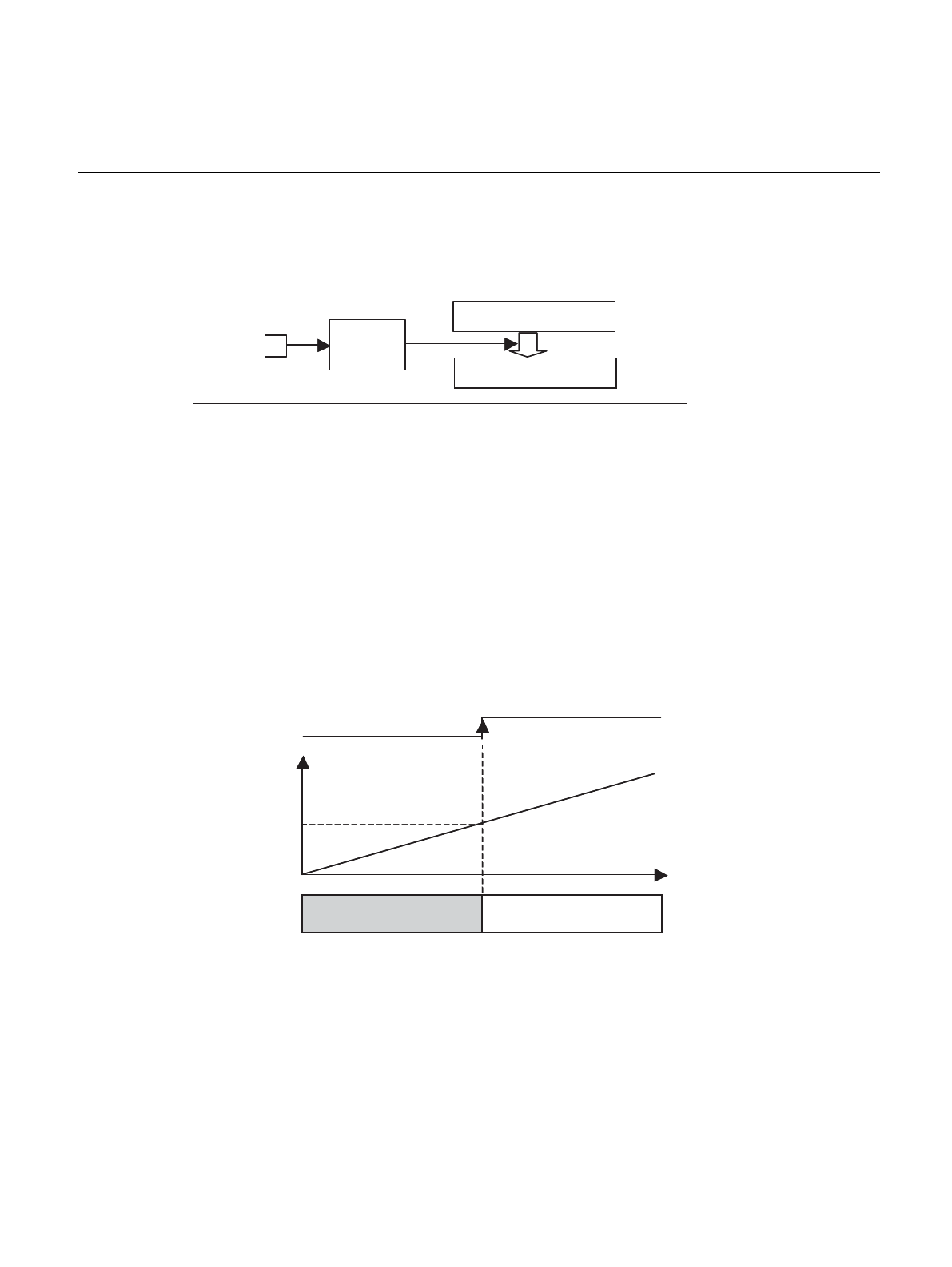
Input Capture records the free-run timer count value using timing detected from an external signal. It is then
possible to calculate the time between signals using the record of the repeated count.
2. Features
• Format: Edge detection circuit + 16 bit buffer (capture register)
• Quantity: 4 groups = 8 channels (input capture channels 0/1, 2/3, 4/5, 6/7)
• Compatible timers: Input capture channels 0/1 use free-run timer 0
Input capture channels 2/3 use free-run timer 1
Input capture channels 4/5 use free-run timer 4
Input capture channels 6/7 use free-run timer 5
• Edge Detection: Rising/falling/both edges
• Interrupt: Edge detection
• Capture value: Timer count value (0000
H
-FFFF
H
)
• Timer: Uses free-run timer 0
• Precision: 4/F
CLKP
, 16/F
CLKP
, 32/F
CLKP
, 64/F
CLKP
(Free-run timer count clock)
Buffer
Capture
Free-run timer 0
Edge
detection
circuit
pin
A
A
Free-run
timer
count value
Captured signal
Buffer value
A
A
t


