831
Chapter 40 Pulse Frequency Modulator
3.Reload Counter Operation
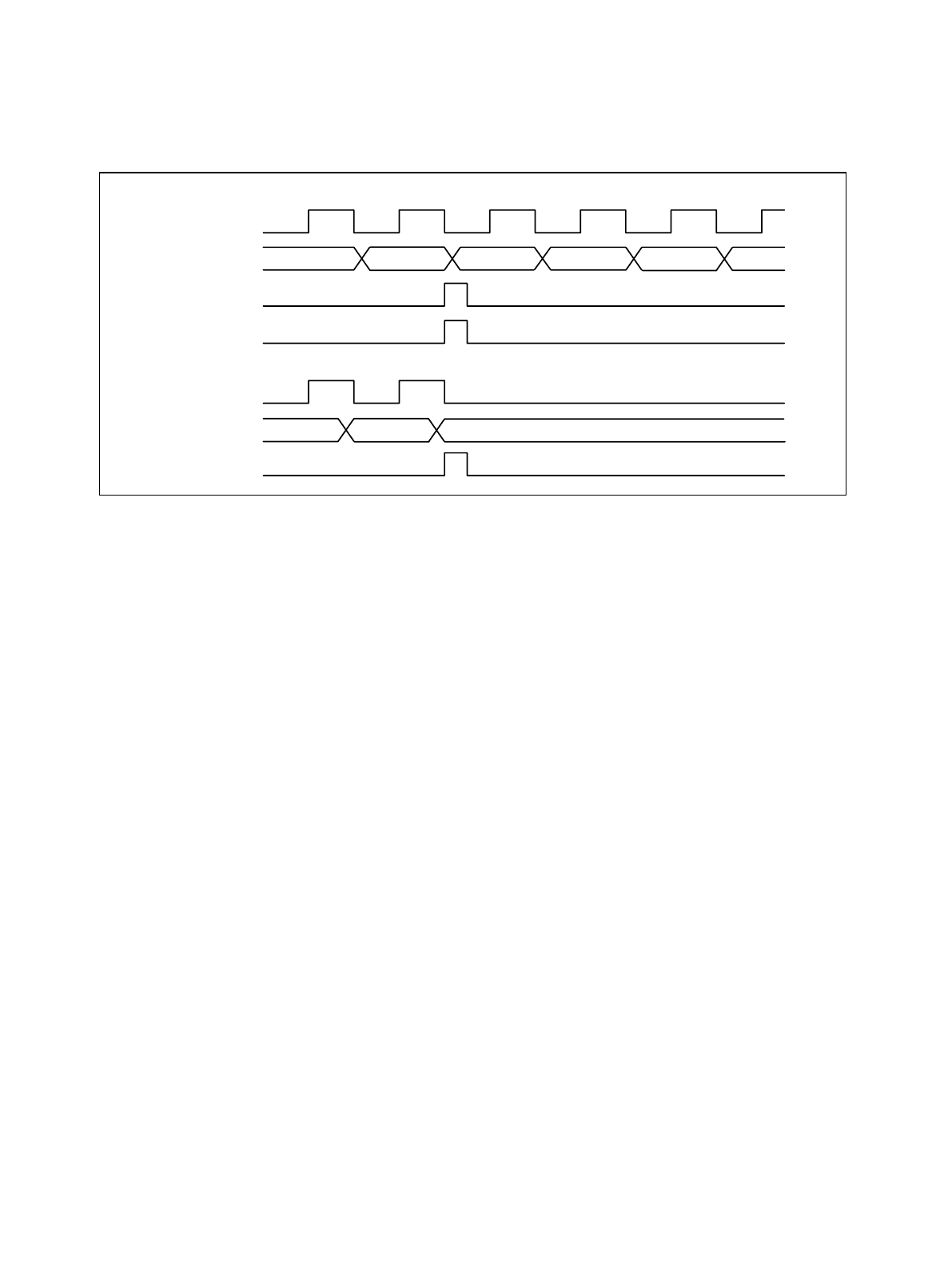
● Underflow operation timing
Figure 3-2 Underflow Operation Timing
■ Counter Operation States
The counter state is determined by the CNTE bit in the control register and the internal WAIT
signal. The available states are CNTE = "0" and WAIT = "1" (STOP state: operation halted),
CNTE = "1" and WAIT = "1" (WAIT state: waiting for a trigger), and CNTE = "1" and WAIT = "0"
(RUN state: operating).
Figure 3-3 shows the transitions between each state.
Count clock
Count clock
Underflow set
Counter
• When RELD = "1"
Data load
Counter
Reload data –1 –1–1
Underflow set
• When RELD = "0"
0000
H
0000H FFFFH


