249
Chapter 18 Timebase Counter
1.Overview
Chapter 18 Timebase Counter
1. Overview
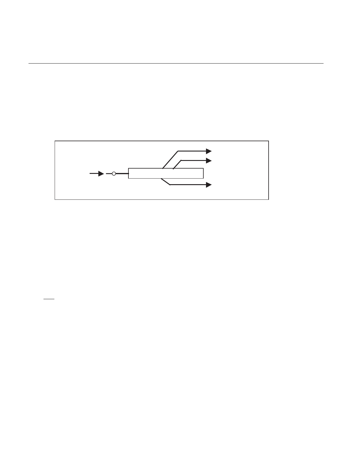
The timebase counter is a 26-bit up-counter that counts the subclock or the main clock divided by two.
When recovering from a state in which the selected clock source for the MCU has been, or may have been,
halted, the MCU automatically changes to the oscillation stabilization wait state to avoid any unstable output
from the oscillator.
During the oscillation stabilization wait time, supply of internal and external clocks is halted and only the
timebase counter continues to operate until the time set by the oscillation stabilization wait time setting has
elapsed.
The timebase counter, timebase timer, and watchdog timer are collectively called the watchdog control unit.
2. Features
2.1 Timebase Counter (when used to generate the oscillation stabilization wait)
Type : 26-bit up-counter
Number : 1
Clock source (F2): Main clock divided by two, or subclock
Clear : Cleared automatically when changing to oscillation stabilization wait state.
2.2 Events that Invoke an Oscillation Stabilization Wait
■ Events that invoke an oscillation stabilization wait using the timebase counter
● Wait time after a settings initialization: Invoked automatically (timebase counter)
• INIT Initial oscillation stabilization wait after pin input
• Watchdog reset
• If the main clock oscillation has not been halted: Oscillation stabilization wait not required
• If the main clock oscillation has halted: Oscillation stabilization wait is required
Example: If a watchdog reset occurs during subclock mode with main clock oscillation halted
● Wait time after recovering from stop mode: Invoked automatically (timebase counter)
• Stop mode cases when clock oscillation circuit is halted:
• The oscillation stabilization wait time for the intended oscillation circuit is required
• Wait time for main PLL to lock is required (if main PLL is used)
• Stop mode cases when clock oscillation circuit is not halted:
Oscillation stabilization wait is not required unless the clock oscillation (main/PLL) has been halted.
● When recovering from abnormal state with main PLL selected
Automatically goes to the oscillation stabilization wait state to allow time for the main PLL to lock.
26-bit counter
Watchdog timer
Time-base timerTime-base counter
Base clock
Oscillation stabilization wait control signal
Time-base counter when used to
generate the oscillation stabilization wait
State transition
control circuit


