964
Chapter 50 Subclock Calibration Unit
2.Block Diagram
2. Block Diagram
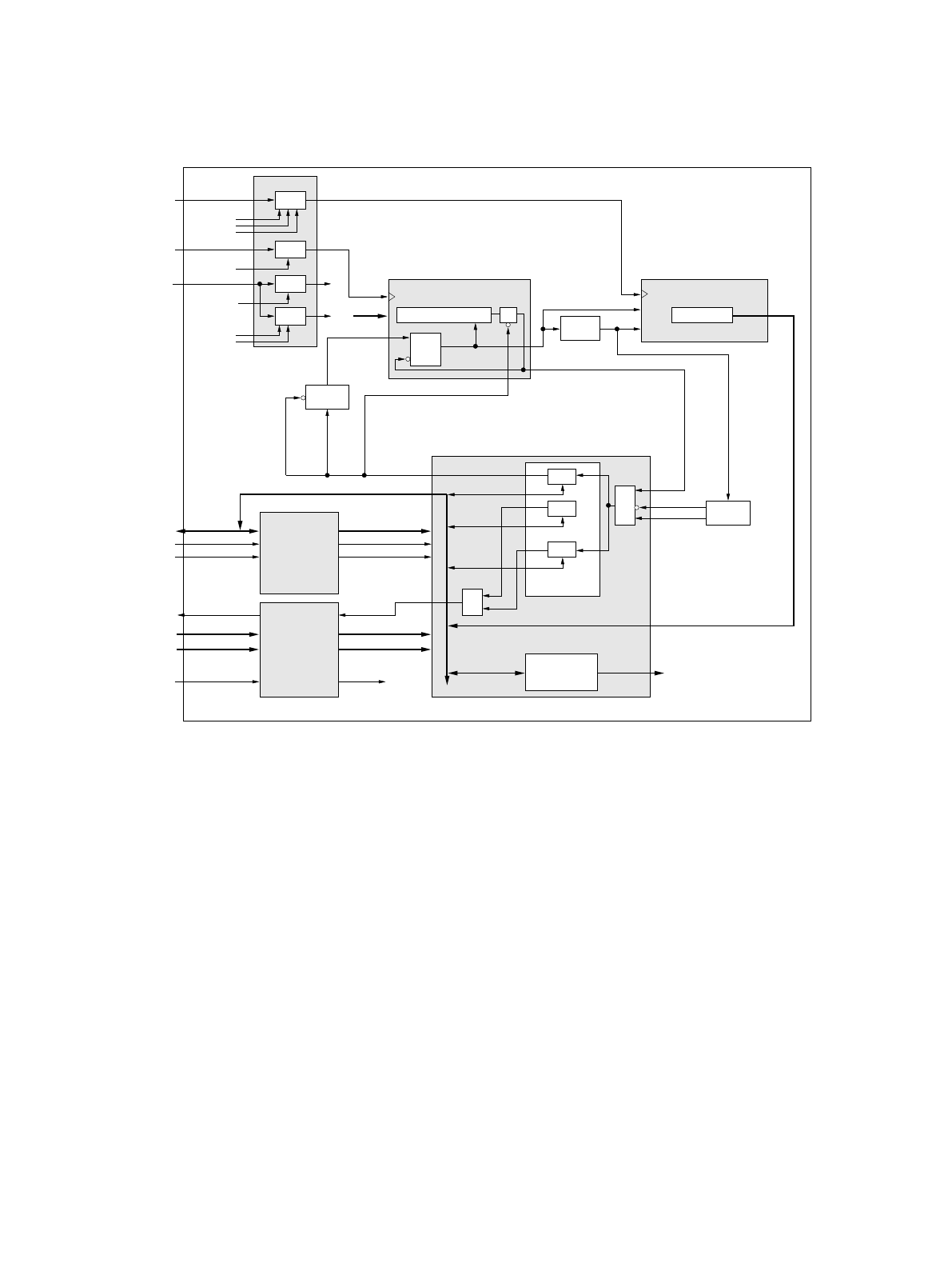
Figure 2-1 Block Diagram of the calibration unit
CLKPG2 = CLKP | (~STRT & RSLEEPB);
CLK4G = OSC4 | ~STRT | (READY & ~RUNS);
UC18CLK
RUN
RUN
READYPULSE
RUNS
RUNS
RUNSS1
&
&
STRT
sync
4->CLKP
sync
32->4
CLKP->32
sync
4MHz
TIMER
UC18TRR
CUTR
32kHz
TIMER
UC18TRD
UC18RBI
CUTR (24 bit)
UC18IO
UC18BUS
RBB
RSLEEPB
RMWB
*_WRB
*_RDB
RSTB
FC18
CLK32G
CUTD
RB
INT_I
CUTD
CUTD (16 bit)
CUCR (3 bit)
CUTR (24 bit)
INT_INT
set / reset
reset
set / reset
reset
READY
RUNSS
&
set
STRT
async
RST
INT
counter (16 bit)
READY
RST
async
READY
STRT
CLKPG2
RSLEEPB
RSLEEPB
RB
RSLEEP
RMW
*_WR
*_RD
RST
INT
CLKP
CLKPG
gate
gate
gate
STRT
gate
STRT
READY
CLK4G
INTEN
STRT
STRT
STRTS
OSC32
OSC4


