800
Chapter 39 Programmable Pulse Generator
4.Registers
4.2 PDUT: PPG Duty Setting Register
Sets the duty of the PPG output waveform.
• PDUT00 (PPG0): Address 0114h (Access: Half-word)
• PDUT01 (PPG1): Address 011Ch (Access: Half-word)
• PDUT02 (PPG2): Address 0124h (Access: Half-word)
• PDUT03 (PPG3): Address 012Ch (Access: Half-word)
• PDUT04 (PPG4): Address 0134h (Access: Half-word)
• PDUT05 (PPG5): Address 013Ch (Access: Half-word)
• PDUT06 (PPG6): Address 0144h (Access: Half-word)
• PDUT07 (PPG7): Address 014Ch (Access: Half-word)
• PDUT08 (PPG8): Address 0154h (Access: Half-word)
• PDUT09 (PPG9): Address 015Ch (Access: Half-word)
• PDUT10 (PPG10): Address 0164h (Access: Half-word)
• PDUT11 (PPG11): Address 016Ch (Access: Half-word)
• PDUT12 (PPG12): Address 0334h (Access: Half-word)
• PDUT13 (PPG13): Address 033Ch (Access: Half-word)
• PDUT14 (PPG14): Address 0344h (Access: Half-word)
• PDUT15 (PPG15): Address 034Ch (Access: Half-word)
(See “Meaning of Bit Attribute Symbols (Page No.10)” for details of the attributes.)
• The PPG Duty Setting registers registers are buffered. Transfers from the buffers to the counter take place
automatically at counter overflow or underflow.
• Set a value smaller than the setting of PPG Period Setting register PCSR in a PPG Duty Setting register.
(See “8. Caution (Page No.821)”.)
• If the same value as set in PPG Period Setting register PCSR is set in a PPG Duty Setting register,
• “H” is always output to (OSEL=”0”) at normal polarity time.
• “L” is always output to (OSEL=”1”) at inverted polarity time.
(The OSEL bit is an output polarity specification bit of the PPG control register PCN.)
• Always access the PPG Duty Setting registers in a half-word (16-bit) format.
(See “8. Caution (Page No.821)”.)
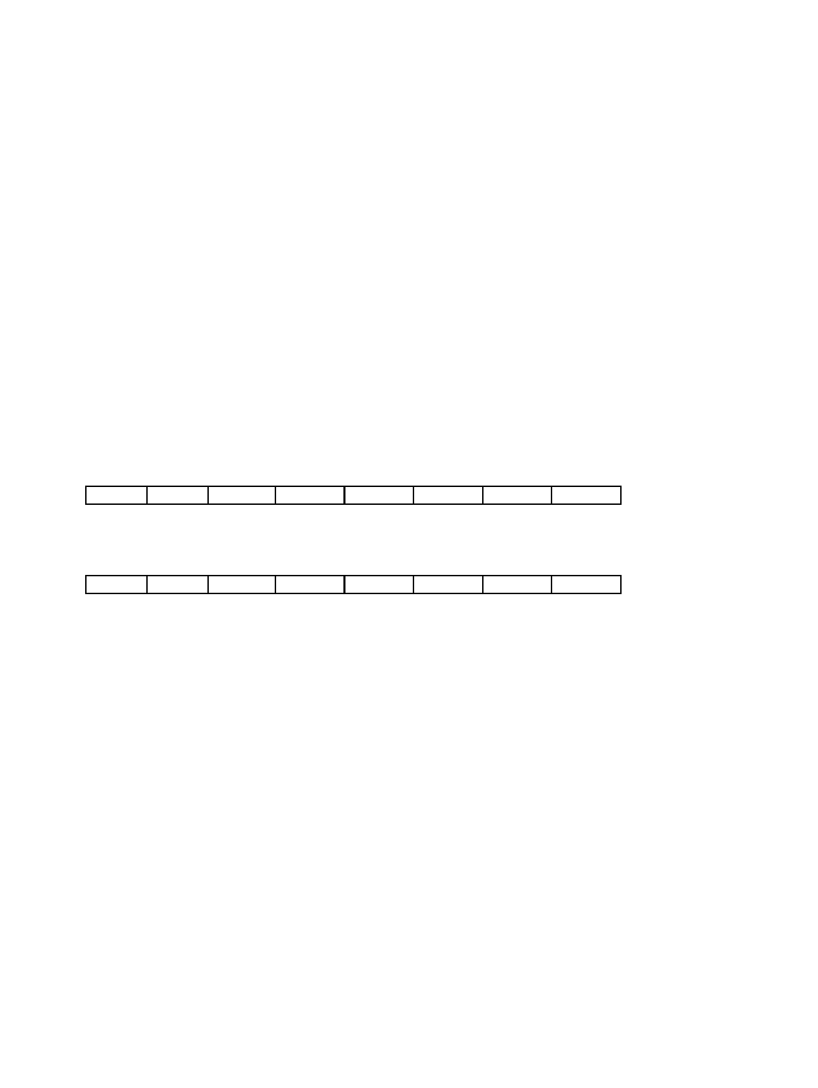
15 14 13 12 11 10 9 8 Bit
D15 D14 D13 D12 D11 D10 D9 D8
X X X X X X X X Initial value
RX, W RX, W RX, W RX, W RX, W RX, W RX, W RX, W Attribute
76543210Bit
D7 D6 D5 D4 D3 D2 D1 D0
X X X X X X X X Initial value
RX, W RX, W RX, W RX, W RX, W RX, W RX, W RX, W Attribute


