


196
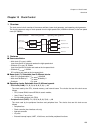
Chapter 13 Clock Control
4.Registers
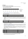
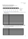
4.4 CSCFG: Clock Source Configuration Register
This register controls the main clock oscillation in subclock mode
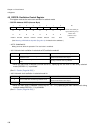
• CSCFG: Address 04AEh (Access: Byte)
(See “Meaning of Bit Attribute Symbols (Page No.10)” for details of the attributes.)
• bit7: EDSU/MPU Enable
• bit6: PLL Lock
• bit5: RC Oscillator Selector
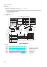
The selected oscillation frequency is supplied to Clock Control Unit (for Subclock Operation) and Flash Security Unit
(change the oscillation to 2 MHz for faster CRC generation). Hardware Watchdog (RC based Watchdog), Real Time
Clock, Calibration Unit, LCD and Clock Supervisor Module are always supplied with 100 kHz independent of this
setting.
• bit4: Clock Monitor MONCLK inverter
See chapter “Clock Monitor (Page No.941)” about information about this function.
• Bit3-0: Clock Source Selection
7 6 5 4 3 2 1 0 bit
EDSUEN PLLLOCK RCSEL MONCKI CSC3 CSC2 CSC1 CSC0
0X00000 0
Initial value (INIT pin
input, watchdog reset)
XXXXXXXX
Initial value
(software reset)
R/W R R/W R/W R/W R/W R/W R/W Attribute
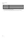
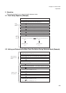
EDSUEN Function
0 EDSU/MPU is (clock) disabled [Initial value]
1 EDSU/MPU is (clock) enabled
PLLLOCK Function
0 PLL is in the un-locked state
1 PLL is in the locked state
RCSEL Function
0 RC oscillation is set to 100 kHz [Initial value]
1 RC oscillation is set to 2 MHz
MONCKI Function
0 MONCLK mark level is low [Initial value]
1 MONCLK mark level is high
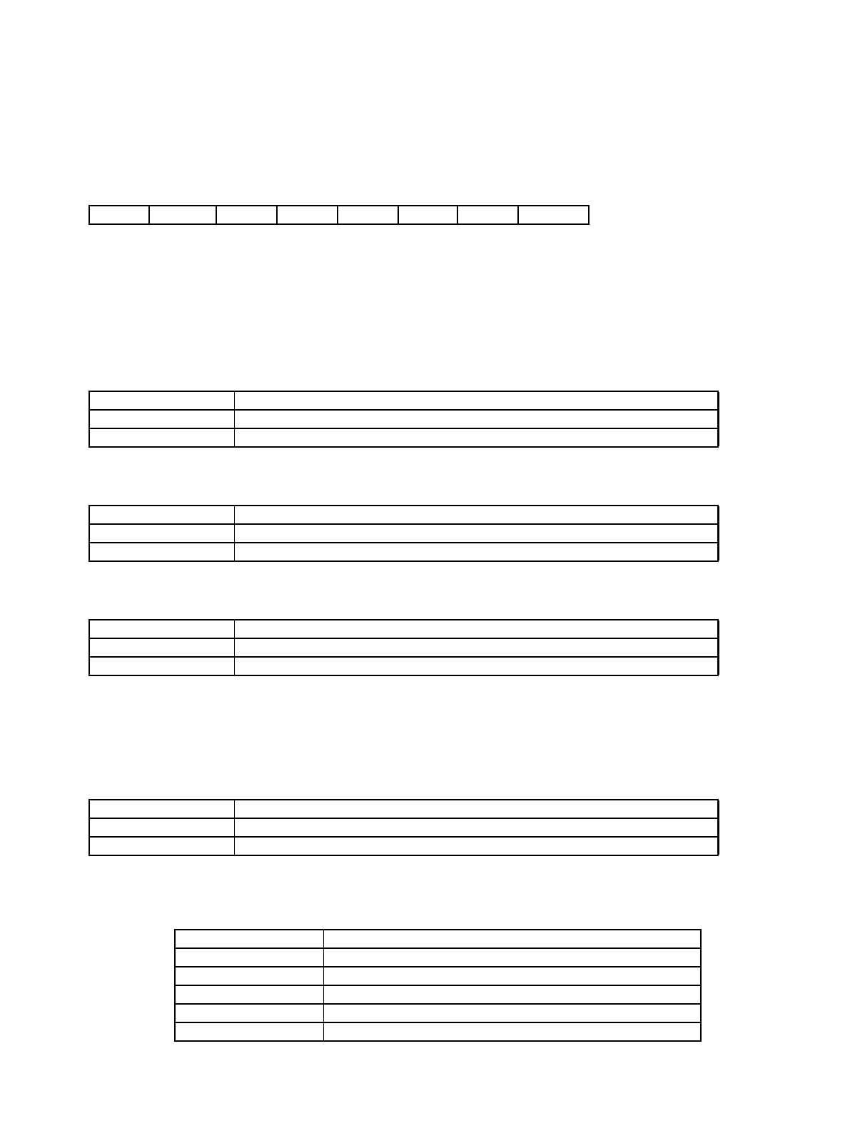
CSC3-CSC0 Function
--00 Real Time Clock is sourced by Main Oscillation
--01 Real Time Clock is sourced by Sub Oscillation
--10 Real Time Clock is sourced by RC Oscillation
--11 Setting prohibited
-0-- Subclock Calibration is sourced by Sub Oscillation