


892
Chapter 44 A/D Converter
3.Registers of A/D Converter
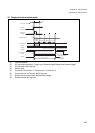
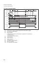
Continuous mode: Repeated A/D conversion cycles from selected channels ANS4 to ANS0 to selected
channels ANE4 to ANE0.
Stop mode: A/D conversion for each channel from selected ANS4 to ANS0 to selected channels ANE4 to
ANE0, followed by a pause. Restart is determined by the occurrence of a start source.
When A/D conversion is started in continuous mode or stop mode, conversion operation continued until
stopped by the BUSY bit.
Conversion is stopped by writing "0" to the BUSY bit.
On activation after forcibly stopping, conversion starts from channel selected ANS4 to ANS0.
All restarts are disabled for any of the timer, external trigger and software start sources in single,
continuous and stop modes.
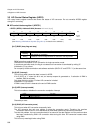
[bit 5] S10
This bit defines resolution of A/D conversion. If this bit set "0", the resolution is 10-bit. In the other case,
resolution is 8-bit and the conversion result is stored to ADCR0.
Initialized to "0" by a reset.
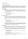
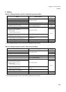
[bit 4 to 0] ACH4-0 (Analog convert select channel)
These bits show current converted channel.
Initialized to "0000" by reset.
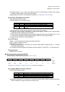
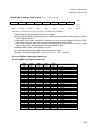
3.3 Data Register (ADCR1, ADCR0)
These registers store the conversion results of the A/D converter. ADCR0 stores lower 8-bit. ADCR1 stores upper
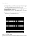
ACH4 ACH3 ACH2 ACH1 ACH0 Converted channel
00000AN0
00001AN1
00010AN2
00011AN3
00100AN4
00101AN5
00110AN6
00111AN7
01000AN8
01001AN9
01010AN10
01011AN11
01100AN12
01101AN13
01110AN14
01111AN15
10000AN16
10001AN17
10010AN18
10011AN19
10100AN20
10101AN21
10110AN22
10111AN23
11000AN24
11001AN25
11010AN26
11011AN27
11100AN28
11101AN29
11110AN30
11111AN31
ACH Function
Reading
Current converted channel is shown during A/D converting (BUSY="1"). If
conversion is halt by forcibly stopping, they shows the stopped channel.
Writing No effect to these bits.