


770
Chapter 37 Output Compare
7.Q & A
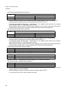
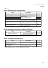
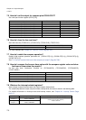
7.5 How do I set the output for compare pins OCU0-OCU7?
Set it with port function register (PFR15[7:0]).
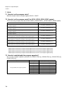
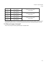
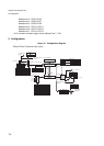
7.6 How do I clear the free-run timer?
Set it with clear bits (TCCS2.CLR), (TCCS3.CLR), (TCCS6.CLR), (TCCS7.CLR).
For other methods, see “Chapter 35 Free-Run Timer (Page No.733)”.
7.7 How do I enable the compare operation?
Enable it with compare operation permission bit (OCS01.CST[1:0]), (OCS23.CST[1:0]), (OCS45.CST[1:0]),
(OCS67.CST[1:0]).
See “7.4 How do I set the initial level of the compare pin output? (Page No.769)”.
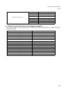
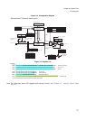
7.8 How do I compare the free-run timer value with the compare register value and clear
the free-run timer when they match?
Do this with timer initialization condition bit (TCCS2.MODE), (TCCS3.MODE), (TCCS6.MODE),
(TCCS7.MODE).
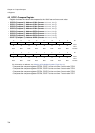
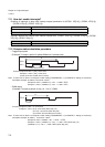
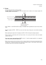
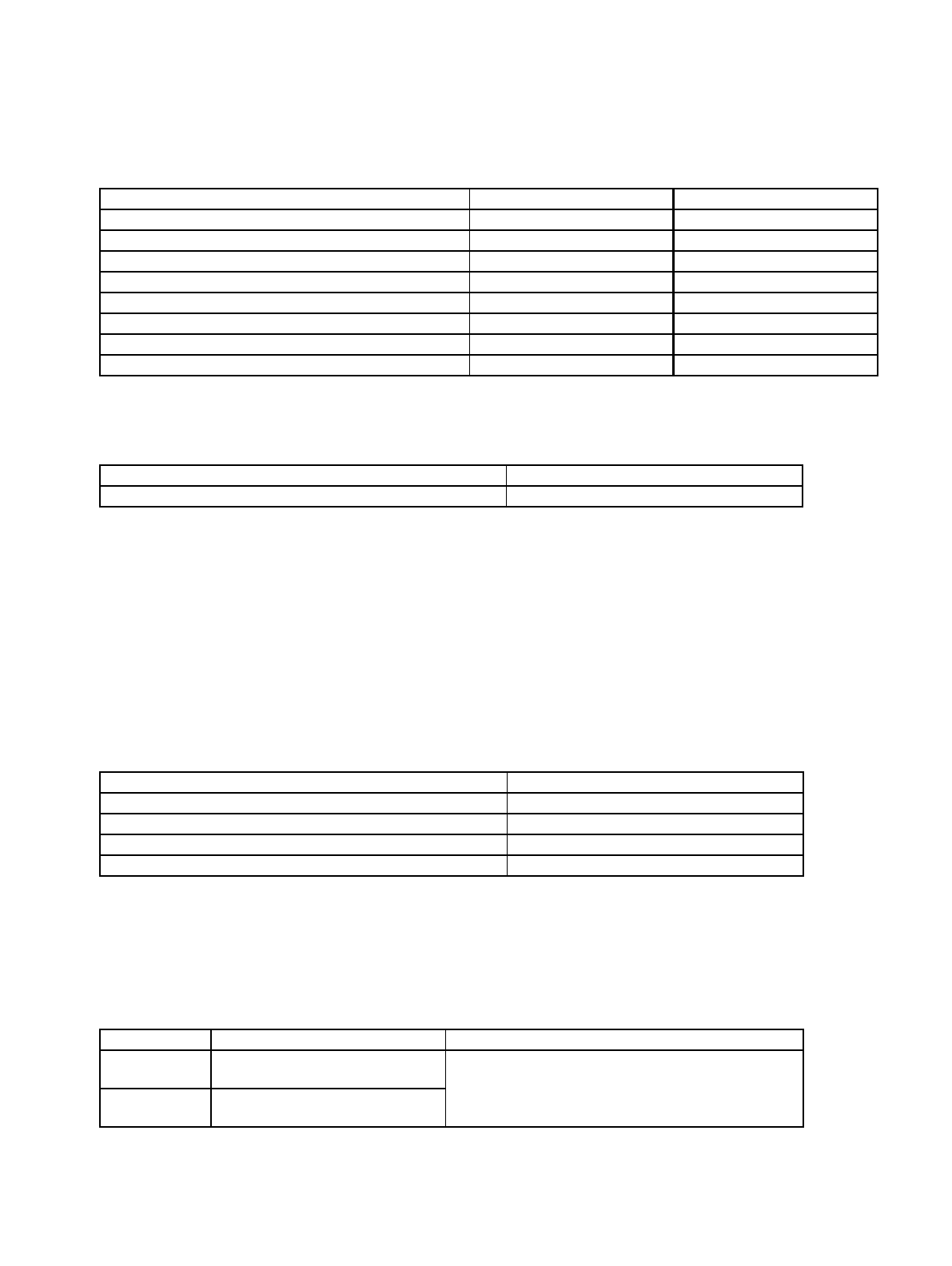
7.9 What are the interrupt-related registers?
Set the output compare interrupt vector and output compare interrupt level.
The relationship between output compare number, interrupt level, and vector is shown in the following table.
For detailed information on interrupt levels and interrupt vectors, see “Chapter 24 Interrupt Control (Page
No.311)”.
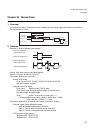
Operation Port function bit Extra port function bit
To set compare 0 pin (OCU0) to output Set PFR15.0 bit to “1” Set EPFR15.0 bit to “0”
To set compare 1 pin (OCU1) to output Set PFR15.1 bit to “1” Set EPFR15.1 bit to “0”
To set compare 2 pin (OCU2) to output Set PFR15.2 bit to “1” Set EPFR15.2 bit to “0”
To set compare 3 pin (OCU3) to output Set PFR15.3 bit to “1” Set EPFR15.3 bit to “0”
To set compare 4 pin (OCU4) to output Set PFR15.4 bit to “1” Set EPFR15.4 bit to “0”
To set compare 5 pin (OCU5) to output Set PFR15.5 bit to “1” Set EPFR15.5 bit to “0”
To set compare 6 pin (OCU6) to output Set PFR15.6 bit to “1” Set EPFR15.6 bit to “0”
To set compare 7 pin (OCU7) to output Set PFR15.7 bit to “1” Set EPFR15.7 bit to “0”
Operation Clear Bit (CLR)
To clear the free-run timer Write “1”
Operation Timer initialization condition bit (MODE)
To clear free-run timer upon compare 0 match Set (TCCS2.MODE) to “1”
To clear free-run timer upon compare 2 match Set (TCCS3.MODE) to “1”
To clear free-run timer upon compare 4 match Set (TCCS6.MODE) to “1”
To clear free-run timer upon compare 6 match Set (TCCS7.MODE) to “1”
Number Interrupt vector (default) Interrupt level setting bit (ICR[4:0])
Output
Compare 0
#100
Address: 0FFE6Ch
Interrupt level register (ICR42)
Address: 046Ah
Output
Compare 1
#101
Address: 0FFE68h