


165
Chapter 10 Standby
8.Caution
8. Caution
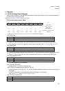
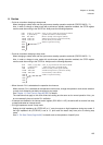
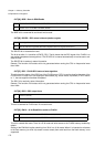
• Points to note when changing to sleep mode
When changing to sleep mode, set the synchronous standby operation enable bit (TBCR.SYNCS= “1”).
Also, in order to change to sleep mode with synchronous standby operation enabled, the STCR register
must be read after writing to the SLEEP bit. Always use the following sequence.
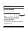
• Points to note when changing to stop mode
When changing to sleep mode, set the synchronous standby operation enable bit (TBCR.SYNCS= “1”).
Also, in order to change to stop mode with synchronous standby operation enabled, the STCR register
must be read after writing to the STOP bit. Always use the following sequence.
• When the main PLL is selected as the operation clock source
When the main PLL is selected as the operation clock source, change the operation clock source selection
to main clock divided by two before changing to stop mode.
See “Chapter 13 Clock Control (Page No.189)” for details.
The restrictions that apply to the clock divide ratio setting are the same as for normal operation. Also, you
do not necessarily have to halt the PLL oscillation.
• If interrupts are disabled in the interrupt control register (ICR=“00011111B”), the device will not recover from stop
or sleep mode when an interrupt occurs.
• Pin high impedance control in stop mode
Setting the high impedance bit (STCR.HIZ) to “1” sets pin outputs to high impedance during stop mode. If
the high impedance bit (STCR.HIZ) is set to “0”, pins retain the states they have prior to entering stop
mode.
See “8. Pin State Table (Page No.96)” for details such as the operation of specific pins.
(LDI #value_of_sleep, R0) ; value_of_sleep contains the write data for STCR.
(LDI #_STCR, R12) ; _STCR is the address of STCR (481H).
STB R0, @R12 ; Write to standby control register (STCR).
LDUB @R12, R0 ; STCR read required for synchronous standby.
LDUB @R12, R0 ; Second dummy read to STCR.
NOP ; NOP x 5 required for timing
NOP
NOP
NOP
NOP
(LDI #value_of_stop, R0) ; value_of_stop contains the write data for STCR.
(LDI #_STCR, R12) ; _STCR is the address of STCR (481H).
STB R0, @R12 ; Write to standby control register (STCR).
LDUB @R12, R0 ; STCR read required for synchronous standby.
LDUB @R12, R0 ; Second dummy read to STCR.
NOP ; NOP x 5 required for timing
NOP
NOP
NOP
NOP