


625
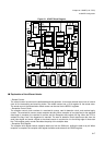
Chapter 32 USART (LIN / FIFO)
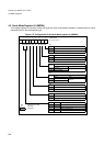
4.USART Registers
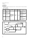
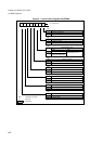
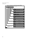
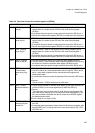
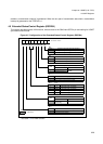
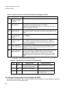
4.3 Serial Status Register 04 (SSR04)
This register checks the transmission statuts, reception status and error status, and enables and disables the
transmission and reception interrupts.
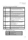
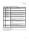
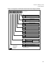
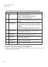
Table 4-4 Bit function of the Serial Mode register 04 (SMR04)
Bit name Function
bit7
bit6
MD1 and MD0:
Operation mode
selection bits
These two bits sets the USART operation mode.
bit5 OTO: One-to-one
external clock
selection bit
This bit sets an external clock directly to the USART’s serial clock.
This function is used for synchronous slave mode operation
bit4 EXT: External clock
selection bit
This bit executes internal or external clock source for the reload
counter
bit3 REST: Restart of
transmission reload
counter bit
If a 1 is written to this bit the reload counter is restarted. Writing 0
to it has no effect. Reading from this bit always returns 0.
bit2 UPCL: USART
programmable clear
bit (Software reset)
Writing a 1 to this bit resets USART immediately. The register
settings are preserved. Possible reception or transmission will cut
off.
All error flags are cleared and the Reception Data Register
(RDR04) contains 00h. Writing 0 to this bit has no effect. Reading
from it always returns 0.
bit1 SCKE: Serial clock
output enable
• This bit controls the serial clock input-output ports.
• When this bit is 0, the SCK04 pin operates as serial clock input
pin. When this bit is 1, the SCK04 pin operates as serial clock
output pin.
<Caution>
• When using the SCK04 pin as serial clock input (SCKE=0) pin,
set the pin as input port. Also, select external clock (EXT = 1)
using the external clock selection bit.
bit0 SOE: Serial data
output enable bit
• This bit enables or disables the output of serial data.
• When this bit is 0, the SOT04 pin outputs the default mark level.
When this bit is 1, the SOT04 pin outputs the transmission data.