


860
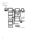
Chapter 41 Up/Down Counter
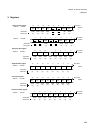
7.Q&A
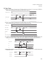
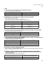
7.15 How do I know that an overflow or underflow has occurred?
Use the overflow detection flag (UDCS.OVFF) and the underflow detection flag (UDCS.UDFF).
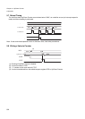
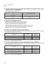
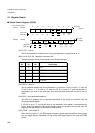
7.16 How do I set the reload/compare value?
Set a value to the reload/compare registers (UDRC). (This value is used as a compare or reload value.)
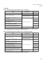
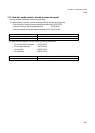
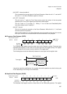
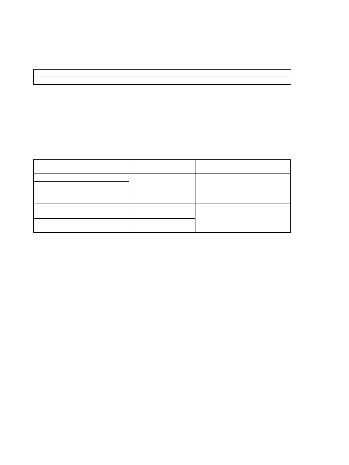
7.17 What are interrupt-related registers?
Configure the up/down counter interrupt vectors and up/down counter interrupt level settings.
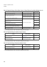
The following table shows the relationship among the up/down counter number, interrupt levels and vectors:
For details on interrupt levels and interrupt vectors, refer to “Chapter 24 Interrupt Control (Page No.311)”.
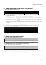
The following interrupt request flags are not automatically cleared:
• Count direction change: UDCC.CDCF
• Compare detection: UDCS.CMPF
• Overflow: UDCS.OVFF
• Underflow: UDCS.UDFF
So, the software must write “0” to the interrupt request flag before control is returned from interrupt processing.
7.18 What interrupts are available and how are they selected?
There are three interrupt causes:
• Count direction change
• compare-match
• overflow/underflow
An interrupt request is made by ORing these three interrupt causes; each interrupt cause cannot be isolated.
Use the interrupt request permission bit to enable a desired interrupt.
OVFF =“1” indicates that Up/Down Counter has been overflowed.
UDFF =“1” indicates that Up/Down Counter has been underflowed.
Interrupt vector
(Default)
Interrupt level set bit (ICR[4:0])
Up/Down Counter 0/1 (16 bit)
#128
Address: 0FFDFCh
Interrupt level register (ICR56) Address:
0478h
Up/Down Counter 0 (8 bit)
Up/Down Counter 1 (8 bit)
#129
Address: 0FFDF8h
Up/Down Counter 2/3 (16 bit)
#130
Address: 0FFDF4h
Interrupt level register (ICR57) Address:
0479h
Up/Down Counter 2 (8 bit)
Up/Down Counter 3 (8 bit)
#131
Address: 0FFDF0h