


830
Chapter 40 Pulse Frequency Modulator
3.Reload Counter Operation
3. Reload Counter Operation
This section describes the operations of the 16-bit reload counter: Internal clock operation and
Underflow operation
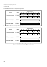
■ Internal Clock Operation
The machine clock divided by 2, 8, 32, 64 or 128 can be selected as the clock source when
operating the counter from an internal clock.
Writing "1" to both the CNTE and TRG bits in the control status register enables and starts
counting simultaneously.
Using the TRG bit as a trigger input is always available when the counter is enabled (CNTE =
"1"), regardless of the operation mode.
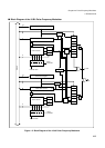
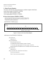
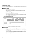
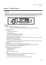
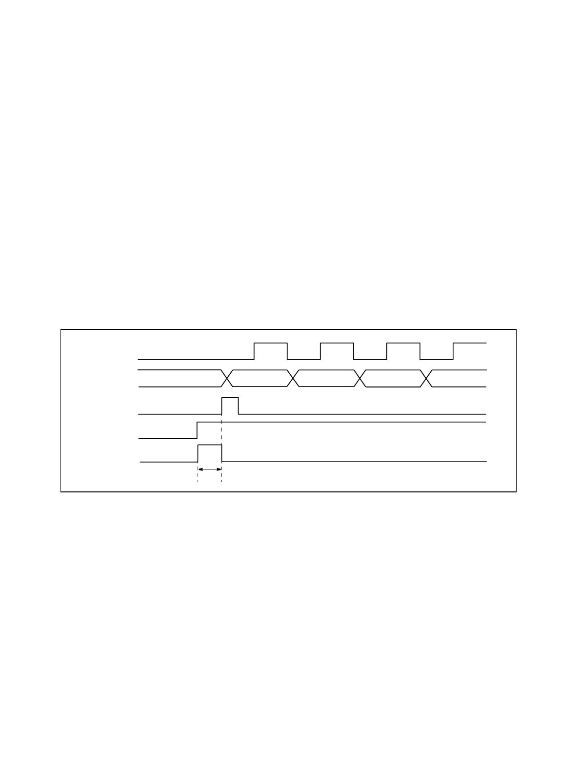
Figure 3-1 shows counter activation and counter operation.
A time f (f: peripheral clock machine cycle) is required from the counter start trigger being input
until the reload register data is loaded into counter.
● Counter activation and operation timing
Figure 3-1 Counter Activation and Operation Timing
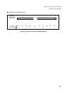
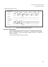
■ Underflow Operation
An underflow occurs when the counter value changes from 0000H to FFFFH. Therefore, an
underflow occurs after "reload register setting + 1" counts.
If the RELD bit in the control register is "1" when the underflow occurs, the contents of the reload
register are loaded into the counter and counting continues. When RELD is "0", counting stops
with the counter at FFFFH.
The UF bit in the control register is set when the underflow occurs. If the INTE bit is "1" at this
time, an interrupt request is generated.
Figure 3-2 shows the operation when an underflow occurs.
Count clock
TRG (register)
Counter
CNTE (register)
Data load
Reload data –1–1–1
φ