605
Chapter 31 External Bus
10.DMA Access Operation
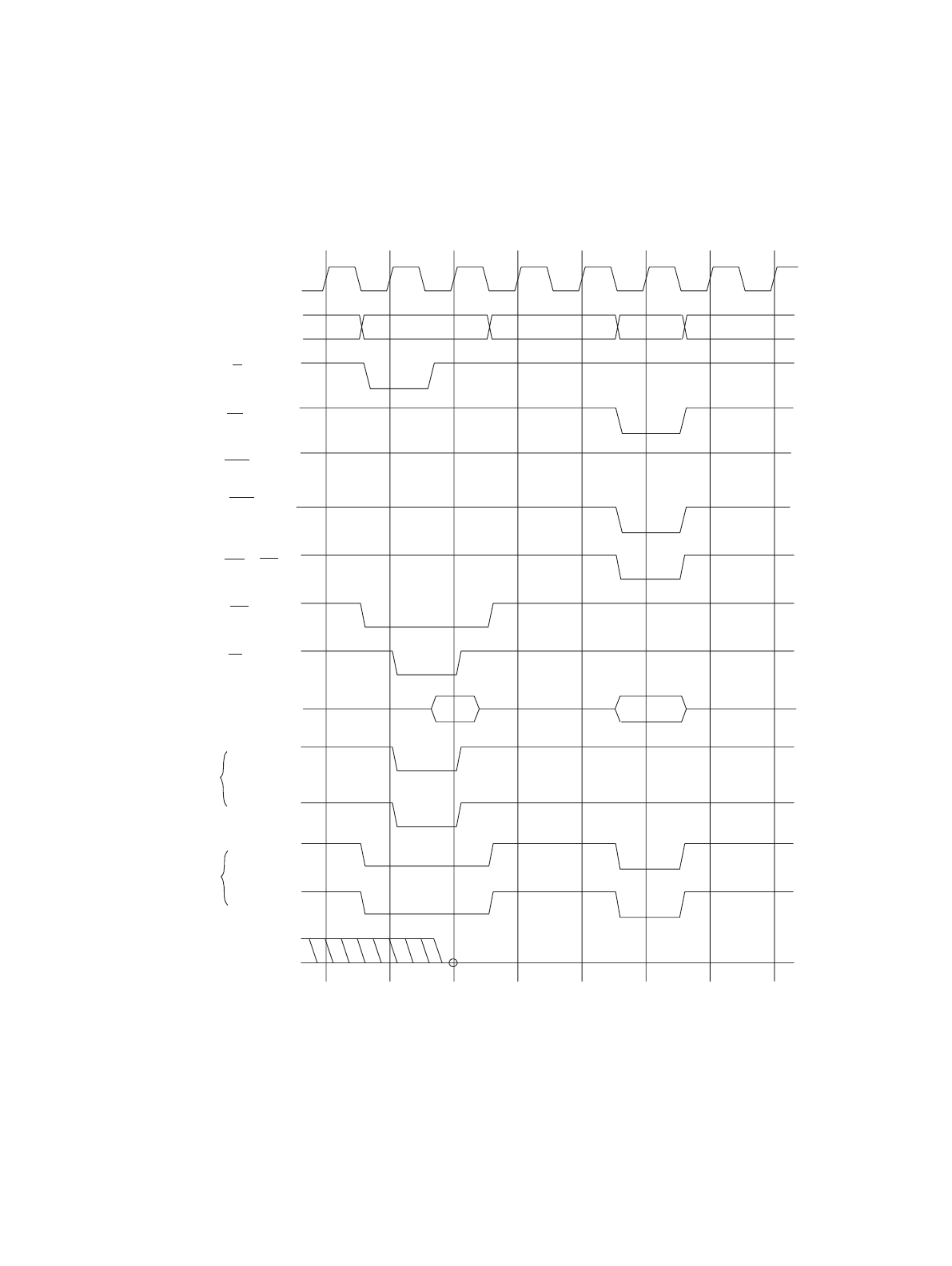
■ 2-Cycle Transfer (I/O -> SDRAM/FCRAM)
Figure 4.10 - 11 shows an operation timing chart assuming TYP3 to TYP0 set to 1000B, AWR set to 0051H, and
IOWR set to 00H.
Figure 10-11 Timing Chart for Two - cycle Transfer (I/O to SDRAM/FCRAM)
10.9 2-Cycle Transfer (SDRAM/FCRAM -> I/O)
This section describes the operation of two - cycle transfer (SDRAM/FCRAM to I/O device).
■ 2-Cycle Transfer (SDRAM/FCRAM -> I/O)
Figure 1.10 - 12 shows a timing chart for two - cycle transfer (SDRAM/FCRAM to I/O)
MCLK
A31 to 0
AS
CSn
memory
address
I/O
address
idle
WRn(SWE)
RD
D31 to 0
CSn
DACKn
DEOPn
DACKn
DEOPn
DREQn
FR30
compatible
mode
Basic mode
SRAS
SCAS


