


575
Chapter 31 External Bus
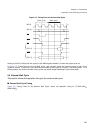
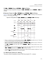
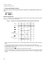
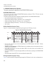
6.Burst Access Operation
the minimum number of the first access cycles is the wait cycles + 2 cycles (three cycles in the timing chart
shown in Figure 6-1 "Timing Chart for Burst Access").
• Setting of the W11-W08 bits of the AWR register enables 0-15 page wait cycles to be inserted. At this point,
the page access cycles can be obtained from the page wait cycles + 1 cycle (Two cycles in the timing chart
shown in Figure 6-1 "Timing Chart for Burst Access")
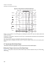
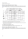
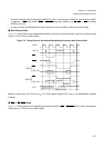
• Setting of the BST bits of the ACR register enables the burst length to be set as 1, 2, 4, or 8. If the burst
length is set to 1, single access mode is set and only the first cycle is repeated. However, if the data bus width
is set to 32 bits (the BST bits of the ACR register are 10
B
), set the burst length to 4 or less (A malfunction
occurs if the burst length is set to 8).
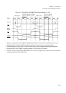
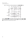
• If burst access is enabled, burst access is used when prefetch access or transfer with a larger size than the
specified data bus width is performed. For example, if word access to an area whose data bus width is set to
8 bits and burst length to 4 is performed, access of 4 bursts is performed once instead of repeating byte
access four times.
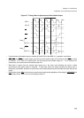
• Since RDY input is ignored in areas for which burst access is set, do not set TYP3-0=0xx1
B
.
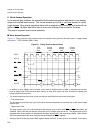
• The LBA and BAA signals are designed for burst FLASH memory. LBA indicates the start of access and BAA
indicates the address increment.
• A31-0 is updated after the wait cycles that were set during burst access.