


791
Chapter 38 Reload Timer
7.Q & A
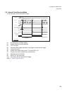
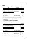
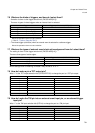
7.6 What are the kinds of triggers, and how do I select them?
• Selection is done via the trigger selection bit (TMCSR.MOD[2:0]).
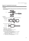
There are 4 types of reload triggers when an internal clock is selected.
Reload is repeated on down counter underflow.
(*: See “8. Caution (Page No.794)”.)
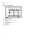
• The reload trigger (activation) when an external event is selected is a software trigger.
Reload is repeated on down counter underflow.
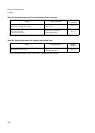
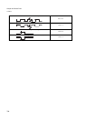
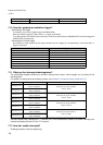
7.7 What are the types of external event clock active edges and how do I select them?
The setting is done via the trigger selection bit (TMCSR.MOD[1:0]).
There are three types of active edges.
MOD2 settings have no meaning, no matter if they are set to “0” or “1”.
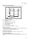
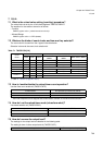
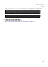
7.8 How do I make a pin a TOT output pin?
Write “1” to the TOT output selection bits (PFR15/EPFR15) to change the port to a TOT pin output.
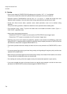
7.9 How do I make the TIN pin into an external event input pin, or an external trigger
input pin?
Write “1” to the TIN input selection bits (PFR14) to change the port to a TIN pin input.
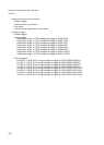
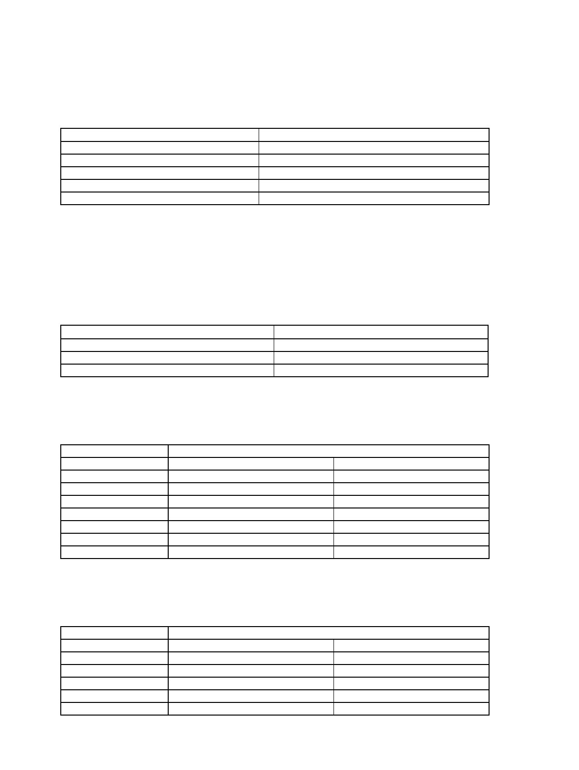
Trigger Trigger specification bit (MOD[2:0])
Software trigger (TRG bit set) Set to “000”
External trigger from TINx pin (rising edge) Set to “001”
External trigger from TINx pin (falling edge) Set to “010”
External trigger from TINx pin (both edges) Set to “011”
—————— “100”, “101”, “110”, “111” are disabled *
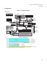
Active edge Trigger selection bit (MOD1-MOD0)
Rising edge Set to “01”
Falling edge Set to “10”
Both edges Set to “11”
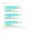
Pin Control bit
TOT0 pin PFR15.0 = ‘1’ EPFR15.0 = ‘1’
TOT1 pin PFR15.1 = ‘1’ EPFR15.1 = ‘1’
TOT2 pin PFR15.2 = ‘1’ EPFR15.2 = ‘1’
TOT3 pin PFR15.3 = ‘1’ EPFR15.3 = ‘1’
TOT4 pin PFR15.4 = ‘1’ EPFR15.4 = ‘1’
TOT5 pin PFR15.5 = ‘1’ EPFR15.5 = ‘1’
TOT6 pin PFR15.6 = ‘1’ EPFR15.6 = ‘1’
TOT7 pin PFR15.7 = ‘1’ EPFR15.7 = ‘1’
Pin Control bit
TIN0 pin PFR14.0 = ‘1’ -
TIN1 pin PFR14.1 = ‘1’ -
TIN2 pin PFR14.2 = ‘1’ -
TIN3 pin PFR14.3 = ‘1’ -
TIN4 pin PFR14.4 = ‘1’ -
TIN5 pin PFR14.5 = ‘1’ -