


401
Chapter 29 MPU / EDSU
3.Break Functions
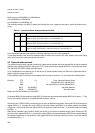
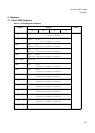
Example: CTC 01 Type: Operand Address Break
EP0 1 Enable break point on BAD0
EP1 1 Enable break point on BAD1
ER0 1 Enable address range function on BAD0, BAD1
EM0 1 Enable address mask function on BAD0, BAD1
BAD0 0x12345200 Set lower break address
BAD1 0x12345300 Set upper break address
BAD2 0xF0000000 Set break mask
Break occurs at 0x02345200 to 0x02345300,or
at 0x12345200 to 0x12345300,or
at 0x22345200 to 0x22345300, etc.
The resulting setting of the BD[1:0] status bits indicates the point, respective the area in which the break has oc-
cured.
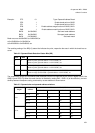
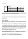
The access data length and read/write break attributes can also be specified by the control register BCR0, bits
OBS[1:0] and OBT[1:0]. When the mask function is disabled by setting EM1 = EM0 = 0 (all bits effective), the rela-
tionship between breakpoint setting, and break by access address is shown below:
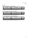
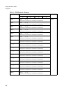
Table 3-2 Operand Break Detection Status Bits (BD)
BD1 BD0
0 1 Match on point (operand address == 0x12345200), or
Match on point (operand address == 0x22345200), etc
1 0 Match on point (operand address == 0x12345300), or
Match on point (operand address == 0x22345300), etc
1 1 Match on range (0x12345200 < operand address < 0x12345300), or
Match on range (0x22345200 < operand address < 0x22345300), etc
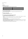
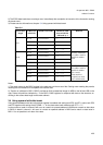
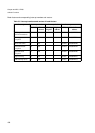
Table 3-3 Operand size and operand address relations
Access data
length
Access
address
Address set in BOA0, BOA1
4n + 0 4n + 1 4n + 2 4n + 3
8 bit
4n + 0 Hit - - -
4n + 1 - Hit - -
4n + 2 - - Hit -
4n + 3 - - - Hit
16 bit
4n + 0 Hit Hit - -
4n + 1 Hit Hit - -
4n + 2 - - Hit Hit
4n + 3 - - Hit Hit