641
Chapter 32 USART (LIN / FIFO)
5.USART Interrupts
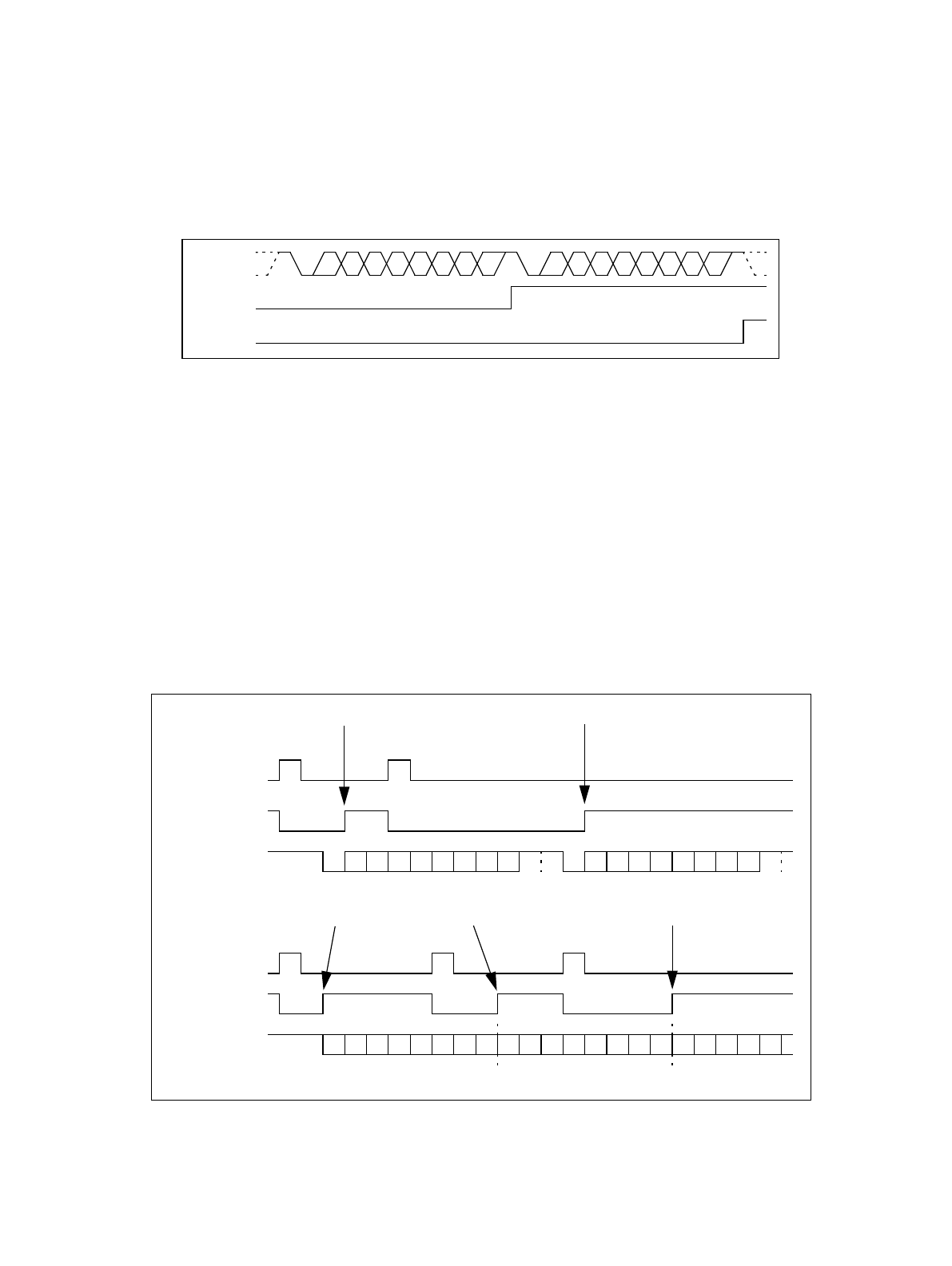
"7p1" and "8N1" (p = "E" [even] or "O" [odd]), all in NRZ data format (ECCR04: INV = 0).
(Note) **ORE only occurs, if the reception data is not read by the CPU (RDRF = 1) and another data frame
is read.
Figure 5-3 ORE set timing
5.2 Transmission Interrupt Generation and Flag Set Timing
A transmission interrupt is generated when the next data to be sent is ready to be written to the output data
register (TDR04).
■ Transmission Interrupt Generation and Flag Set Timing
A transmission interrupt is generated, when the next data to be send is ready to be written to the Transmission
Data Register (TDR04), i. e. the TDR04 is empty, and the transmission interrupt is enabled by setting the
Transmission Interrupt Enable (TIE) bit of the Serial Status Register (SSR04) to "1".
The Transmission Data Register Empty (TDRE) flag bit of the SSR04 indicates an empty TDR04. Because the
TDRE bit is "read only", it only can be cleared by writing data into TDR04.
The following figure demonstrates the transmission operation and flag set timing for the four modes of USART.
Figure 5-4 Transmission operation and flag set timing
(Note) The example in figure 5-4 does not show all possible transmission options for mode 0. Here it is:
"8p1" (p = "E" [even] or "O" [odd]), ECCR04: INV = 0. Parity is not provided in mode 3 or 2, if SSM =
0.
Receive
data
RDRF
ORE
Mode 0, 1 or 3:
TDRE
serial output
Mode 2 (SSM = 0):
TDRE
serial output
transmission interrupt occurs transmission interrupt occurs
D0 D1 D2 D3 D4 D5 D6 D7 D0 D1 D2 D3 D4 D5 D6 D7 D0 D1 D2 D3 D4
ST D0 D1 D2 D3 D4 D5 D6 D7 SP ST D0 D1 D2 D3 D4 D5 D6 D7 SP
P
AD
P
AD
transmission interrupt occurs transmission interrupt occurs
ST: Start bit D0 ... D7: data bits P: Parity SP: Stop bit AD: Address/data selection bit (mode1)
write to TDR04
write to TDR04


