


639
Chapter 32 USART (LIN / FIFO)
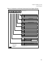
5.USART Interrupts
• - Framing error, i. e. a stop bit was expected, but a "0"-bit was received: FRE
• - Parity error, i. e. a wrong parity bit was detected: PE
If at least one of these flag bits above go "1" and the reception interrupt is enabled
(SSR04: RIE = 1), a reception interrupt request is generated.
If the Reception Data Register (RDR04) is read, the RDRF flag is automatically cleared to "0". Note that this is
the only way to reset the RDRF flag. The error flags are cleared to "0", if a "1" is written to the Clear Reception
Error (CRE) flag bit of the Serial Control Register (SCR04). The RDR04 contains only valid data if the RDRF
flag is "1" and no error bits are set.
Note, that the CRE flag is "write only" and by writing a "1" to it, it is internally held to "1" for one CPU clock
cycle.
■ Transmission Interrupt
If transmission data is transferred from the Transmission Data Register (TDR04) to the transfer shift register
(this happens, if the shift register (or FIFO) is empty and transmission data exists), the Transmission Data
Register Empty flag bit (TDRE) of the Serial Status Register (SSR04) is set to "1". In this case an interrupt
request is generated, if the Transmission Interrupt Enable (TIE) bit of the SSR04 was set to "1" before.
Note, that the initial value of TDRE (after hardware or software reset) is "1". So an interrupt is generated
immediately then, if the TIE flag is set to "1". Also note, that the only way to reset the TDRE flag is writing data
to the Transmission Data Register (TDR04).
■ LIN Synchronization Break Interrupt
This paragraph is only relevant, if USART operates in mode 0 or 3 as a LIN slave.
If the bus (serial input) goes "0" (dominant) for more than 11 bit times, the LIN Break Detected (LBD) flag bit of
the Extended Status/Control Register (ESCR04) is set to "1". Note, that in this case after 9 bit times the
reception error flags are set to "1", therefore the RIE flag has to be set to "0" or the RXE flag has to be set to
"0", if only a LIN synch break detect is desired. In the other case a reception error interrupt would be
generated first, and the interrupt handler routine has then to wait for LBD = 1.
The interrupt and the LBD flag are cleared after writing a "1" to the LBD flag. This makes sure, that the CPU
has detected the LIN synch break, because of the following procedure of adjusting the serial clock to the LIN
master.
■ LIN Synchronization Field Edge Detection Interrupts
This paragraph is only relevant, if USART operates in mode 0 or 3 as a LIN slave. After a LIN break detection
the next falling edge of the reception bus is indicated by USART. Simultaneously an internal signal connected
to the ICU is set to "1". This signal is reset to "0" after the fifth falling edge of the LIN Synchronization Field. In
both cases the ICU4 generates an interrupt, if "both edge detection" and the ICU1/5 interrupt are enabled. The
difference of the ICU4 counter values is the serial clock multiplied by 8. Dividing it by 8 results in the new
detected and calculated baud rate for the dedicated reload counter. This value - 1 has then to be written to the
Baud Rate Generator Registers (BGR1/0).There is no need to restart the reload counter, because it is
automatically reset if a falling edge of a start bit is detected.
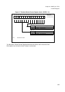
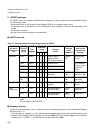
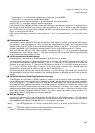
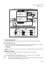
■ Bus Idle Interrupt
If there is no reception activity on the SIN04 pin, the RBI flag bit of the ECCR04 goes "1". The TBI flag bit
respectively goes "1", when no data is transmitted. If the Bus Idle Interrupt Enable bit (BIE) of the ECCR04 is
set and both bus idle flag bits (TBI and RBI) are "1", an interrupt is generated.
(Note) The TBI flag goes also "0" if there is no bus activity, but a "0" is written to the SIOP bit, if SOPE is
"1".
(Note) TBI nd RBI cannot be used in mode 2 (synchronous communication).
Figure 5-1 illustrates how the bus idle interrupt is generated