514
Chapter 31 External Bus
2.External Bus Interface Registers
select area.
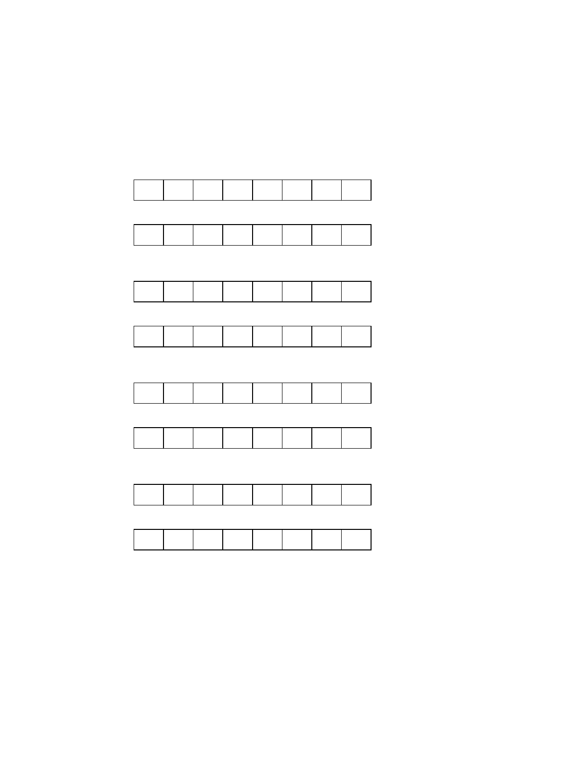
Figure 2-2 "Configuration of Area Configuration Registers 0-7 (ACR0-7)" shows the configuration of area
configuration registers 0-7 (ACR0-7).
Figure 2-2 Configuration of Area Configuration Registers 0-7 (ACR0-7) (Continued on next page)
ACR0H
0000 0642
H
ASZ3 ASZ2 ASZ1 ASZ0 DBW1 DBW0 BST1 BST0 1111**00
B
1111**00
B
00000000
B
00000000
B
Xxxxxxxx
B
xxxxxxxx
B
W/R
ACR0L
76543210
76543210
76543210
76543210
0000 0643
H
SREN PFEN WREN 0 TYP3 TYP2 TYP1 TYP0 W/R
ACR1H
0000 0646
H
ASZ3 ASZ2 ASZ1 ASZ0 DBW1 DBW0 BST1 BST0 W/R
ACR1L
0000 0647
H
SREN PFEN WREN LEND TYP3 TYP2 TYP1 TYP0 xxxxxxxx
B
Xxxxxxxx
B
xxxxxxxx
B
xxxxxxxx
B
xxxxxxxx
B
xxxxxxxx
B
xxxxxxxx
B
xxxxxxxx
B
Xxxxxxxx
B
xxxxxxxx
B
W/R
ACR2H
0000 064A
H
ASZ3 ASZ2 ASZ1 ASZ0 DBW1 DBW0 BST1 BST0 W/R
ACR2L
0000 064B
H
SREN PFEN WREN LEND TYP3 TYP2 TYP1 TYP0 W/R
ACR3H
0000 064E
H
ASZ3 ASZ2 ASZ1 ASZ0 DBW1 DBW0 BST1 BST0 W/R
ACR3L
0000 064F
H
SREN PFEN WREN LEND TYP3 TYP2 TYP1 TYP0 W/R
15 14 13 12 11 10 9 8
15 14 13 12 11 10 9 8
15 14 13 12 11 10 9 8
15 14 13 12 11 10 9 8
Initial value
INIT RST Access


