222
Chapter 16 Clock Supervisor
2.Clock Supervisor Register
2. Clock Supervisor Register
This section lists the Clock Supervisor Control Register and describes the function of each bit in
detail.
■ Clock Supervisor Control Register (CSVCR)
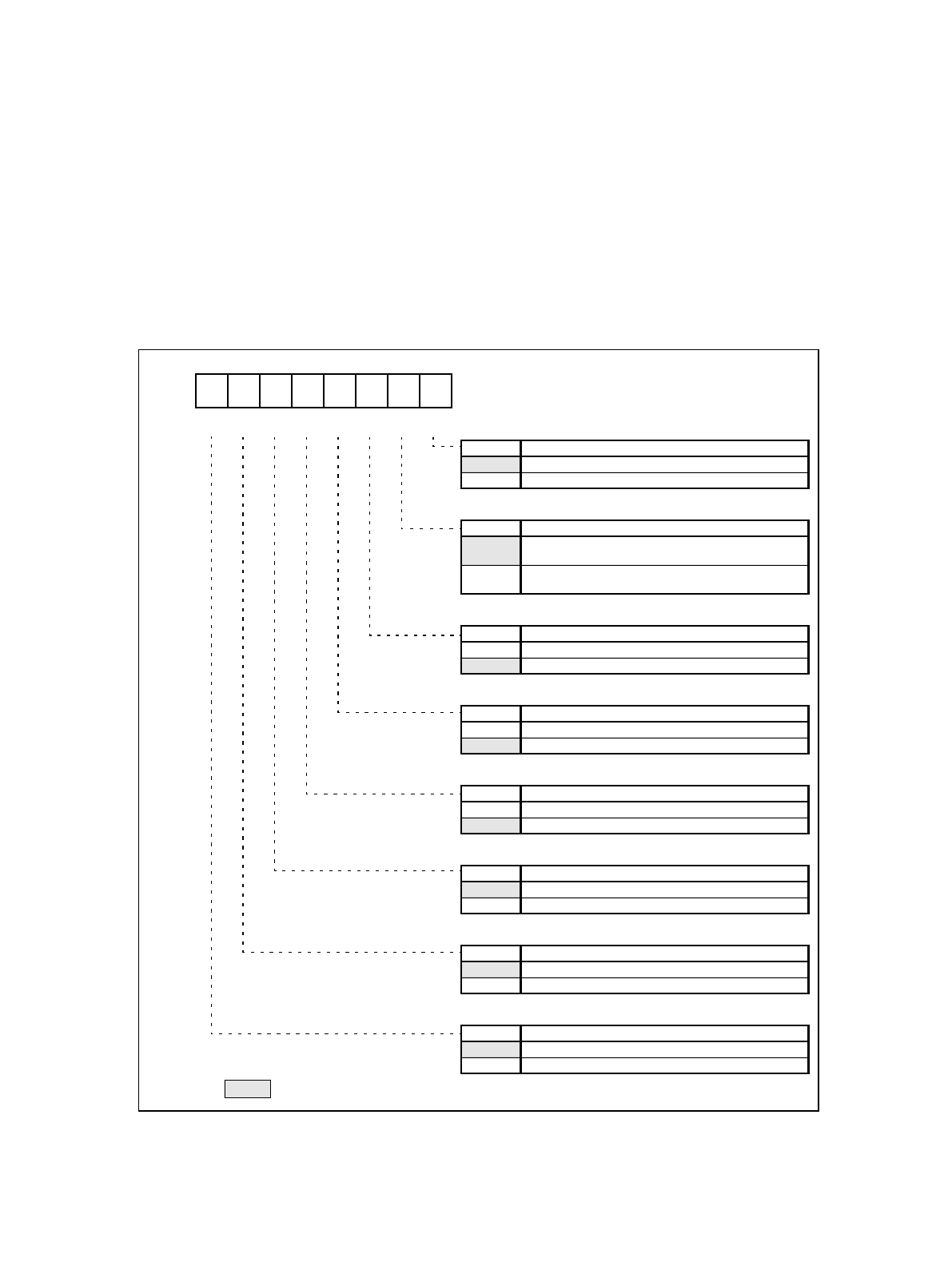
The Clock Supervisor Control Register (CSVCR) sets the operation mode of the Clock Supervisor. Figure 2-1
shows the configuration of the Clock Supervisor Control Register.
Figure 2-1 Configuration Clock Supervisor Control Register (CSVCR)
76543210
B
R/W R R R/W
R/W
R/W R/W R/W
bit0
OUTE Output enable
0 Do not enable ports for MM and SM output
1 Enable ports for MM and SM output
bit1
SRST Sub-clock mode reset
0
do notperform resetupon transition frommain clock to
sub-clock modes if sub-clock is already missing
1
perform reset upon transition from main clock to sub-
clock modes if sub-clock is already missing
bit2
SSVE Sub-clock supervisor enable
0 disable sub-clock supervisor
1 enable sub-clock supervisor
bit3
MSVE Main clock supervisor enable
0 disable main clock supervisor
1 enable main clock supervisor
bit4
RCE RC oscillator enable
0 disable RC-oscillator
1 enable RC-oscillator
bit5
SM Sub-clock missing
0 Missing sub-clock has not been detected
1 Missing sub-clock has been detected
bit6
MM Main clock missing
0 Missing main clock has not been detected
1 Missing main clock has been detected
bit7
SCKS Sub clock select (only used for single clock devices)
0 32k oscillation used as subclock
1 RC oscillation used as subclock
R/W : Readable and writable
R : Read only
: Initial value
0 0 0 1 1 1 0 0
OUTE
SCKS
MM SM RCE
MSVE
SSVE SRST
Initial Value
H
0004AD


