


852
Chapter 41 Up/Down Counter
5.Operation
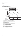
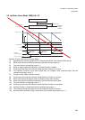
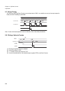
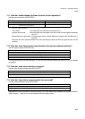
5.5 Phase Difference Count Mode (Multiply by 4) CMS[1:0]=“11”
Frequency multiplied by 4 in phase difference count mode:
On the rising and falling edges at the BIN pin, Up/Down Counter counts up or down, depending on the voltage
level at the AIN pin, and on the rising and falling edges at the AIN pin, Up/Down Counter counts up or down,
depending on the voltage level at the BIN pin.
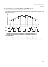
• Count up Conditions:
• When the voltage level at the AIN pin detected on the rising edge at the BIN pin is “H”
• When the voltage level at the AIN pin detected on the falling edge at the BIN pin is “L”
• When the voltage level at the BIN pin detected on the rising edge at the AIN pin is “L”
• When the voltage level at the BIN pin detected on the falling edge at the AIN pin is “H”
• Count down Conditions:
• When the voltage level at the AIN pin detected on the rising edge at the BIN pin is “L”
• When the voltage level at the AIN pin detected on the falling edge at the BIN pin is “H”
• When the voltage level at the BIN pin detected on the rising edge at the AIN pin is “H”
• When the voltage level at the BIN pin detected on the falling edge at the AIN pin is “L”
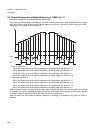
When Up/Down Counter is used to count encoder output, high precise counting of rotation angles and number
of revolutions, as well as detecting of rotation directions, can be achieved by applying encoder output signals
of phase A, phase B and phase Z to the AIN, BIN and ZIN pins, respectively.
Note that when this count mode is selected, selection of the edge to be detected using CES1 or CES0 is
disabled.
Time
AIN
BIN
Count value