


403
Chapter 29 MPU / EDSU
3.Break Functions
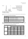
2) The EDSU data break does not always occur immediately after completion of execution of the instruction causing
the break event.
3) Please see also information at chapter 3.4 Using operand with data break
Notes:
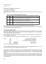
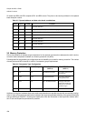
1) The mask values for the BAD0 register in the table are a minimum set of bits. Setting more masking bits permits
masking bits not needed to be compared with transfer data.
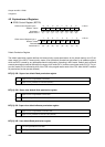
2) "Position of valid data in BAD1, BAD0" provides an 8-bit hexadecimal image for MSB on the left and LSB on the
right. Data at bit positions indicated by * in the BAD1, BAD0 registers is compared with data on the data bus, ac-
cording to the access data length and access address.
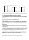
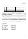
3.4 Using operand with data break
Using operand address with data value break together is enabled with setting both EP3 and EP1, and/or both EP2
and EP0 together with setting the bit COMB = ’1’ for the data value break mode set with CTC = ’11’.
In other words: a break in channel 0 will occur at a match on operand address in BAD2 and a match on data value
in BAD0. A break in channel 1 will occur at a match on operand address in BAD3 and a match on data value in
BAD1. It is not possible to mix them vice versa.
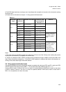
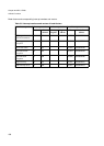
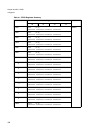
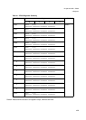
Table 3-4
Access data
length
Address set
to BAD3/2
MASK set to BAD0 Position of valid
data in BAD1/0
(indicated by *)
Remarks
8 bit
4n + 0 0x00FFFFFF **-- ----
4n + 1 0xFF00FFFF --** ----
4n + 2 0xFFFF00FF ---- **--
4n + 3 0xFFFFFF00 ---- --**
16 bit
4n + 0 0x0000FFFF **** ---- Possibly intended to
use address mask in
BAD3 for address
bit 0
4n + 1 0x0000FFFF **** ----
4n + 2 0xFFFF0000 ---- ****
4n + 3 0xFFFF0000 ---- ****
32 bit
4n + 0 0x00000000 **** **** Possibly intended to
use address mask in
BAD3 for address
bits 1 and 0;
Data mask not
required, two chan-
nels could be used
4n + 1 0x00000000 **** ****
4n + 2 0x00000000 **** ****
4n + 3 0x00000000 **** ****