566
Chapter 31 External Bus
5.Operation of the Ordinary bus interface
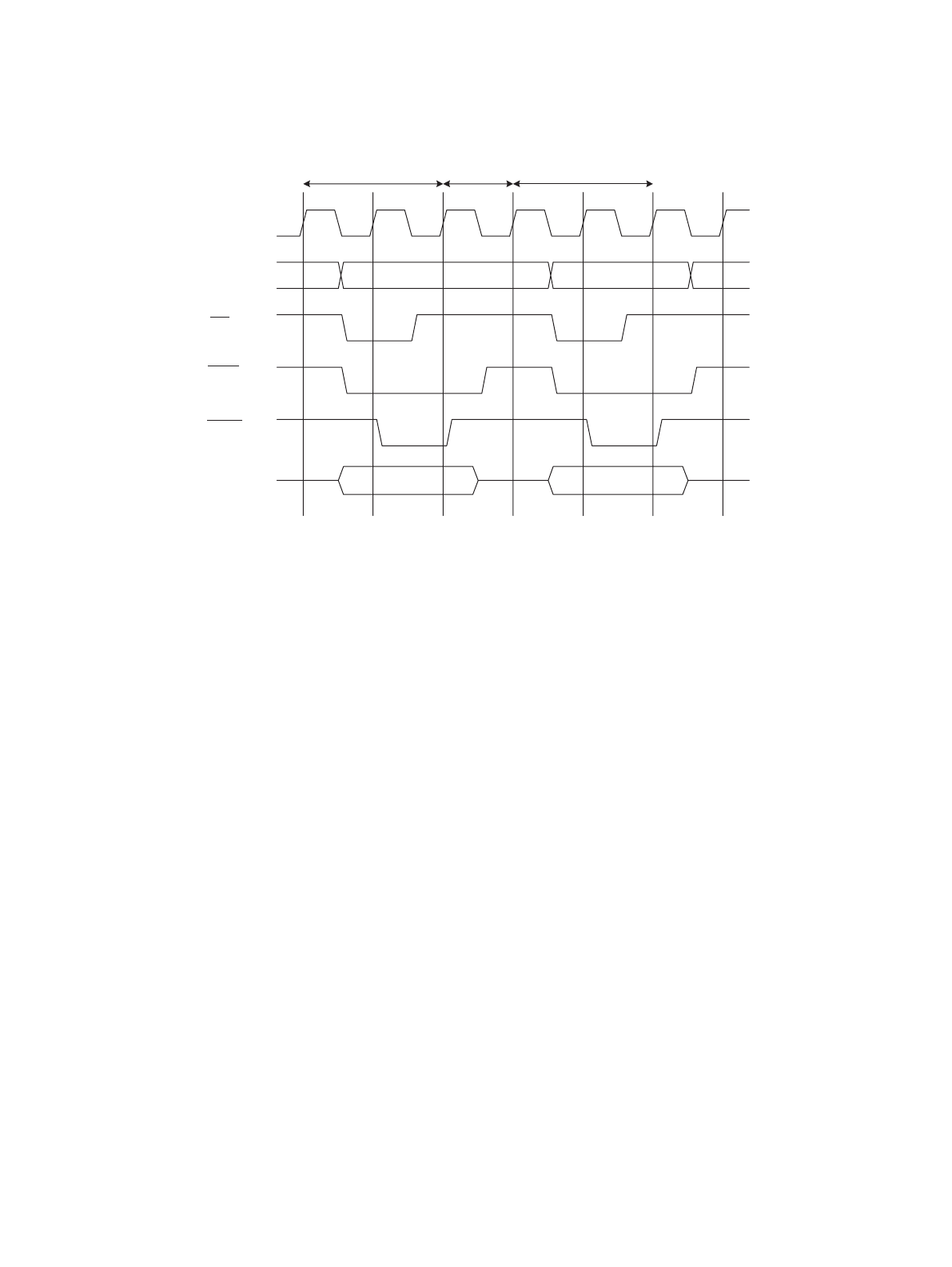
Figure 5-4 Timing Chart for the Write -> Write Operation
• Setting of the W05/W04 bits of the AWR register enables 0-3 write cycles to be inserted.
• After all of the write cycles, recovery cycles are generated.
• Write recovery cycles are also generated if write access is divided into phases for access with a bus width
wider than that specified.
5.5 Auto-Wait Cycle
This section shows the operation timing for the auto-wait cycle.
■ Auto-Wait Cycle Timing
Figure 5-5 "Timing Chart for the Auto-Wait Cycle" shows the operation timing for (TYP3-0=0000
B
, AWR=2008
H
).
Write WriteWrite recovery *
MCLK
AS
CSn
WRn
D[31:0]
A[31:0]


