


874
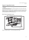
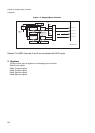
Chapter 43 Stepper Motor Controller
2.Registers
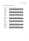
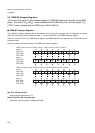
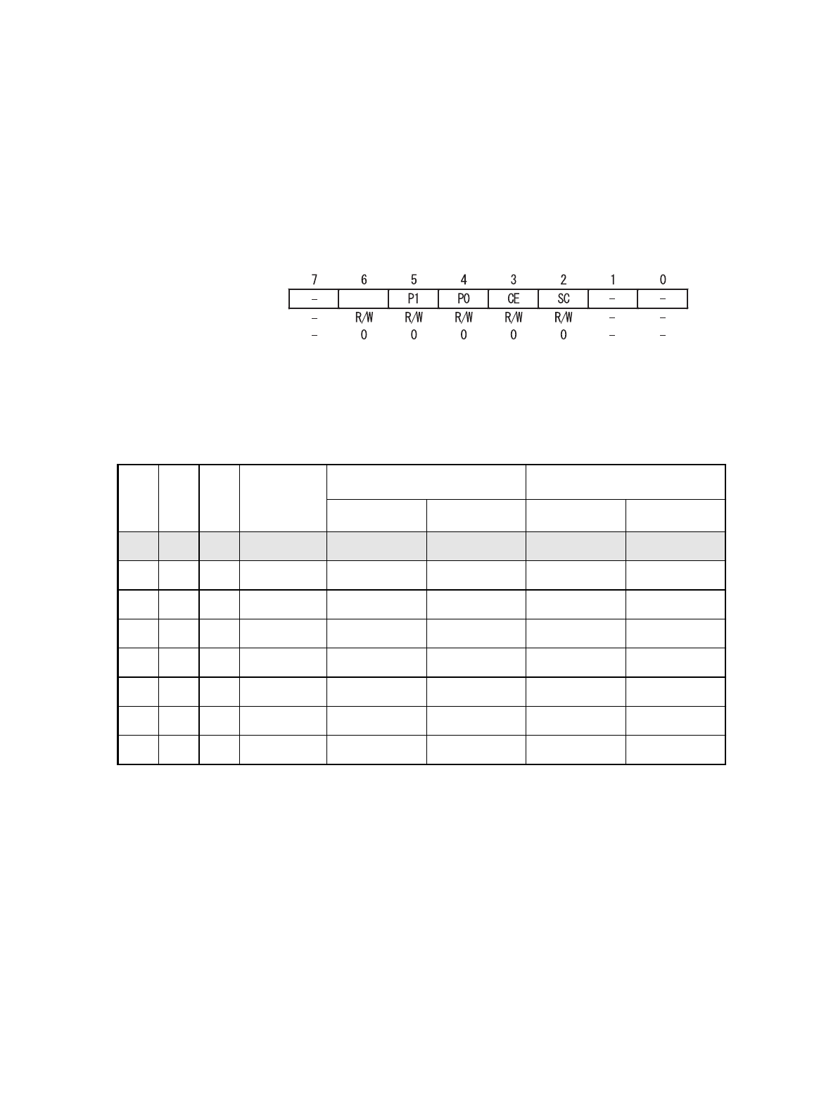
2.2 PWM Control Register
The PWM control register starts/stops the stepping motor controller, performs interrupt control
and performs setting of external output pins, etc., for the stepping motor controller.
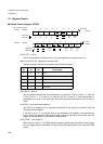
■ PWM Control Register
[bit 7] Reserved bit
Always set the reserved bit to "0".
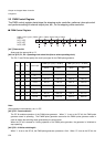
[bit 6 to 4] P2, P1, P0: Operating clock select bits (bits to select operating clock)
The P2, P1 and P0 bits specify the clock input signal for the PWM pulse generator.
Note:
After operation clock selection, set 1 in CE.
[bit 3] CE: Count enable bit
The CE bit enables operation of the PWM pulse generator. When "1" is set to the CE bit, the PWM pulse
generator starts its operating. The PWM2 pulse generator starts after the PWM1 pulse generator starts in
order to reduce the switching noise generated by the output driver.
When the CE bit is cleared to 0 during operation of the PWM pulse generator, the generator is initialized to
stop operating.
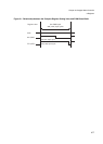
[bit 2] SC: 8/10 bits switching bit
When "1" is set to the SC bit, the PWM pulse generator operates at 10 bit. When "0" is set to the SC bit, the
P2 P1 P0 Clock input
PWM cycle (at F
cp
= 32 MHz) PWM cycle (at F
cp
= 40 MHz)
SC=0 SC=1 SC=0 SC=1
0 0 0
F
CP
8.0 us 32.0 us 6.4 us 25.6 us
001
F
CP
/4
32.0 us 128.0 us 25.6 us 102.4 us
010
F
CP
/5
40.0 us 160.0 us 32.0 us 128.0 us
011
F
CP
/6
48.0 us 192.0 us 38.4 us 153.6 us
100
F
CP
/8
64.0 us 256.0 us 51.2 us 204.8 us
101
F
CP
/10
80.0 us 320.0 us 64.0 us 256.0 us
110
F
CP
/12
96.0 us 384.0 us 76.8 us 307.2 us
111
F
CP
/16
128.0 us 512.0 us 102.4 us 409.6 us
F
CP
: Peripheral clock CLKP
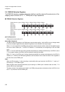
0x0C1, 0x0C3
0x0C5, 0x0C7
0x0C9, 0x0CB
Address
PWM Control register (PWC0, PWC1, PWC2, PWC3, PWC4, PWC5)
P2