653
Chapter 32 USART (LIN / FIFO)
7.USART Operation
LIN break Interrupt is enabled (LBIE = 1) USART will generate a reception interrupt, if a synchronization break of
the LIN master is detected, and indicates it with the LBD flag of the ESCR04. Writing a "0" to this bit clears the
interrupt. The next step is to analyze the baud rate of the LIN master. The first falling edge of the Synch Field is
detected by USART. The USART signals it then to the Input Capture Unit (ICU1/5) via a rising edge of an internal
connection. The fifth falling edge resets the ICU signal. Therefore the ICU has to be configured for the LIN input
capture (PFR14.4=1, EPFR14.4=1) and its interrupts have to be enabled (ICS4). The values of th ICU counter
register after the first Interrupt (a) and after the second interrupt (b) yield the BGR value:
without timer overflow:BGR value = (b - a) / 8 ,
with timer overflow: BGR value = (max - b + a) / 8 ,
where max is the timer maximum value at which the overflow occurs.
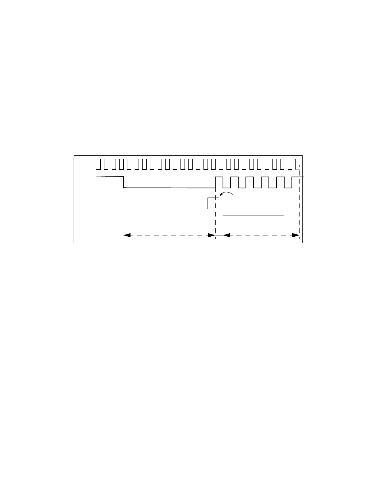
The figure 7-6 shows a typical start of a LIN message frame and the behavior of the USART.
Figure 7-6 USART behavior as slave in LIN mode
■ LIN bus timing
Serial
clock
Synch break Synch field
Serial
Input
(LIN bus)
LBD
(e. g. 14 Tbit)
LBR cleared
by CPU
Internal
ICU
Signal


