


151
Chapter 9 Reset
9.MCU Operation Mode
9. MCU Operation Mode
After release of a reset, the MCU starts operation in the mode specified by the mode pins and mode data.
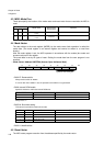
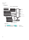
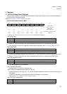
Operation mode Bus mode Single chip mode
Internal ROM/external bus mode
External ROM/external bus mode
Access mode 32-bit bus width
16-bit bus width
8-bit bus width
9.1 Bus Modes and Access Modes
■ Bus mode
The bus mode controls internal ROM operation and the external access function. The bus mode is specified
by the mode setting pins (MD2, MD1, MD0) and internal ROM enable bit (Mode-Vector. ROMA).
The FR60 has the following three bus modes.
● Single chip mode
In this mode, internal I/O, internal RAM, and internal ROM are available but access to other areas is
disabled. External pins are used either by the peripheral functions or as general-purpose ports. Pins cannot
be used as bus pins. This mode can not be used when using the fixed mode/reset vector as implemented
on most of the MB91460 series devices.
● Internal ROM, external bus mode
In this mode, internal I/O, internal RAM, and internal ROM are available, and access to areas for which
external access is enabled results in access to the external area. Some external pins function as bus pins.
● External ROM, external bus mode
In this mode, internal I/O and internal RAM are available but access to internal ROM is prohibited. Access
to internal ROM areas and areas for which external access is enabled results in access to the external
area. Some external pins function as bus pins.
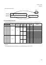
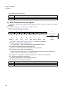
■ Access mode
The access mode controls the width of the external data bus and is set by the WTH[1:0] bits in the mode data.