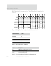
Static memory controller
154
NS9750 Hardware Reference
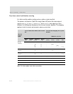
Byte lane control and databus steering
For little and big endian configurations, address right-justified
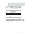
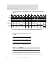
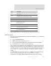
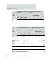
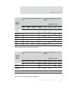
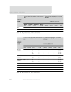
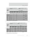
The tables in this section (Table 79 through Table 125) show the relationship of
signals
HSIZE[2:0], HADDR[1:0], ADDROUT[1:0], and BLSOUT[3:0] and mapping of data
between the AHB system databus and the external memory databus. This mapping
applies to both the static and dynamic memory controllers.
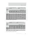
Access: Read, little endian, 8-bit external
bus
External data mapping on to system
databus
Internal
transfer
width HRDATA to DATA
HSIZE
[2:0]
HADDR
[1:0]
ADDROUT
[1:0]
BLSOU
T [0]
[31:24] 23:16] [15:8] [7:0]
Word (4
transfers)
010 -- 11
10
01
00
0
0
0
0
[7:0]
-
-
-
-
[7:0]
-
-
-
-
[7:0]
-
-
-
-
[7:0]
Halfword (2
transfers)
001 1- 11
10
0
0
[7:0]
-
-
[7:0]
-
-
-
-
Halfword (2
transfers)
001 0- 01
00
0
0
-
-
-
-
[7:0]
-
-
[7:0]
Byte 000 11 11 0 [7:0] - - -
Byte 000 10 10 0 - [7:0] - -
Byte 000 01 01 0 - - [7:0] -
Byte0000000 0---[7:0]
Table 79: Little endian read, 8-bit external bus


