


www.digiembedded.com
489
BBus Bridge
4 The state machine enters a loop where four NOP words are written to the Fifo
Data register and four words are read from the Fifo Data register. The RXFDB and
RRDY fields are continuously monitored in Status Register A. The Fifo Data
register is read only when a valid word is present.
5 The CPU is taken out of reset and serial channel B is placed into reset. Normal
operation begins with the ARM fetching an instruction from system memory
address 0x00000000.
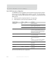
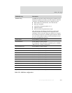
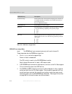
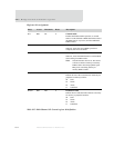
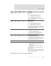
Internal word counter Action(s) taken
0x01 This word is discarded. The word is composed of the bytes shifted in while the
read command and address are being shifted out, as well as the pad entry in the
header.
0x02 Num words entry. This entry is saved locally.
0x03 SDRAM config entry. This entry is saved locally.
0x04 – 0x14 Memory controller entries. These entries are written to the appropriate memory
controller register.
0x015 Field I in the memory controller Dynamic Control register is set to PALL, which
allows several refresh operations to occur while the next 12 words are shifted in
from the SPI-EEPROM.
0x016 – 0x20 No action taken. The word is discarded.
0x021
Field I in the memory controller Dynamic Control register is set to
MODE. A system memory read operation is performed, to the address
specified by the SDRAM config entry. This configures the external
SDRAM devices.
Field I in the memory controller Dynamic Control register is set to
NORMAL. Dynamic Configuration Register 0 is read and field B is set as
required by the memory controller for normal operation.
0x022 – End Each word is written to system memory starting at address 0x00000000. End is
defined by the internal word counter matching the num words entry (0x02)
Table 294: Boot algorithm actions