Overview
544
NS9750 Hardware Reference
Overview
The I
2
C module is designed to be a master and slave. The slave is active only when
the module is being addressed during an I
2
C bus transfer; the master can arbitrate for
and access the I
2
C bus only when the bus is free (idle) — therefore, the master and
slave are mutually exclusive.
Physical I
2
C bus
The physical I
2
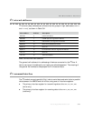
C bus consists of two open-drain signal lines: serial data (SDA) and
serial clock (SCL). Pullup resistors are required; see the standard I
2
C bus specification
for the correct value for the application. Each device connected to the bus is
software-addressable by a unique 7- or 10-bit address, and a simple master/slave
relationship exists at all times.
A master can operate as a master-transmitter (writes)) or a master-receiver (reads).
The slaves respond to the received commands accordingly:
In transmit mode (slave is read), the host interface receives character-
based parallel data from the ARM. The module converts the parallel data to
serial format and transmits the serial data to the I
2
C bus.
In receive mode (slave is written to), the I
2
C bus interface receives 8-bit-
based serial data from the I
2
C bus. The module converts the serial data to
parallel format and interrupts the host. The host’s interrupt service routine
reads the parallel data from the data register inside the I
2
C module. The
serial data stream synchronization and throttling are done by modulating the
serial clock. Serial clock modulation can be controlled by both the
transmitter and receiver, based in their hosts’ service speed.
The I
2
C is a true multi-master bus with collision detection and arbitration to prevent
data corruption when two or more masters initiate transfer simultaneously. If a
master loses arbitration during the addressing stage, it is possible that the winning
master is trying to address the transfer. The losing master must therefore
immediately switch over to its slave mode.
The on-chip filtering rejects spikes on the bus data line to preserve data integrity.
The number of ICs that can be connected to the same bus is limited only by a
maximum bus capacity of 400 pf.


