


Two-channel AHB DMA controller (AHB bus)
474
NS9750 Hardware Reference
Two-channel AHB DMA controller (AHB bus)
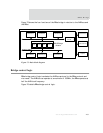
Each DMA channel moves data from the source address to the destination address.
Transfers can be specified as burst-oriented to maximize AHB bus efficiency. All
transfers are executed in two steps:
1 Data is moved from the source address to an 8-entry buffer in the DMA control
logic.
2 Data is moved from the 8-entry buffer to the destination address.
These steps are repeated until the DMA transfer is complete. Note that optimum
performance is achieved when the source and destination addresses are word-
aligned.
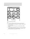
Initiating a DMA transfer
There are two ways to initiate a DMA transfer: processor-initiated and
external-peripheral initiated.
When the processor initiates the DMA transfer, it performs these steps:
1 Sets up the required buffer descriptors.
2 Configures the appropriate DMA Channel 1/2 Control register (see "DMA Channel
1/2 Control register" on page 491).
3 Writes a 1 to the channel enable (CE) and channel go (CG) fields in the DMA
Channel 1/2 Control register (see "DMA Channel 1/2 Control register" on page
491).
The external peripheral initiates a DMA transfer by asserting the appropriate
REQ
signal. Software must set up the required buffer descriptors and configure the DMA
Channel 1/2 Control register (including setting the
CE field to 1) before asserting the
REQ signal.
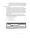
DMA buffer descriptor
All DMA channels in NS9750 use a buffer descriptor. When a DMA channel is activated,
it reads the DMA buffer descriptor pointed to by the Buffer Descriptor Pointer register
(see "Buffer Descriptor Pointer register" on page 491). A DMA buffer descriptor is
always fetched using an AHB INCR4 transaction, to maximize AHB bus bandwidth.