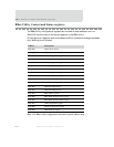
DMA Control and Status registers
516
NS9750 Hardware Reference
DMA Status/Interrupt Enable register
Address: DMA1
9000 0014 / 0034 / 0054 / 0074 / 0094 / 00B4 / 00D4 / 00F4 / 0114 / 0134 /
0154 / 0174 / 0194 / 01B4 / 01D4 / 01F4
Address: DMA2
9011 0014 / 0034 / 0054 / 0074 / 0094 / 00B4 / 00D4 / 00F4 / 0114 / 0134 /
0154 / 0174 / 0194 / 01B4 / 01D4 / 01F4
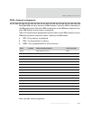
The DMA Status/Interrupt Enable register contains DMA transfer status as well as
control information for generating interrupt signals. There is a DMA Status/Interrupt
Enable register for each channel within each DMA controller module.
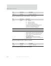
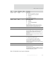
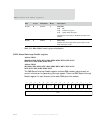
D15:10 R STATE 0 State field
0x00 Idle
0x20 Transfer in progress
0x18 Update buffer descriptor
Describes the current state of the DMA controller state
machine.
D09:00 R INDEX 0 Index value
Identifies the current byte offset pointer relative to the
buffer descriptor pointer.
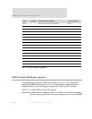
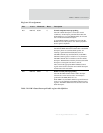
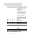
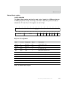
Bits Access Mnemonic Reset Description
Table 313: BBus DMA Control register bit definition
13121110987654321015 14
31 29 28 27 26 25 24 23 22 21 20 19 18 17 1630
ECIE NRIENCIP ECIP
BLEN
PCIECAIENRIP
CAIP
PCIP Not used NCIE
WRAP
IDONE
LAST FULL


