www.digiembedded.com
837
Timing
Clock timing
Note:
All AC characteristics are measured with 10pF, unless otherwise noted.
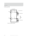
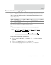
The next three timing diagrams pertain to clock timing.
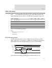
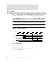
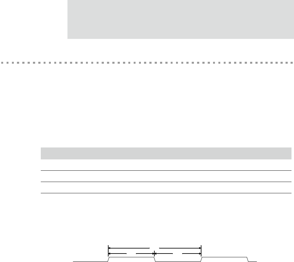
USB crystal/external oscillator timing
Table 481 describes the values shown in the USB crystal/external oscillator timing
diagram (Figure 146).
Note:
1 If using a crystal, the tolerance must be ±100 ppm or better.
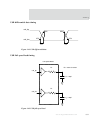
Figure 146: USB crystal/external oscillator timing
Parm Description Min Max Unit Notes
UC1 x1_usb_osc cycle time 20.831 20.835 ns 1
UC2 x1_usb_osc high time (UC1/2) x 0.4 (UC1/2) x 0.6 ns
UC3 x1_usb_osc low time (UC1/2) x 0.4 (UC1/2) x 0.6 ns
Table 481: USB crystal/external oscillator timing parameters
UC1
UC2UC2 UC3
UC1
UC3
x1_usb_osc


