


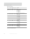
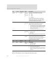
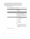

System configuration registers
298
NS9750 Hardware Reference
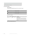
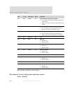
D09:08 R CS1DW
HW strap
boot_strap[
4],
boot_strap[
3]
Chip select 1 data width HW strap setting
00 8 bits
01 16 bits
10 32 bits
11 Reserved
Status bits indicating the hardware strap setting of
external memory chip select 1 data width. The data
width can be changed by writing to the appropriate
control register in the memory controller.
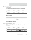
D07 R/W MCCM HW strap
boot_strap[
2]
Memory controller clocking mode HW strap setting
Status bit indicating the hardware strap setting of
external memory controller clocking mode.
0 Command delayed mode. Commands are launched
on a 90-degree phase-shifted AHB clock, and AHB
clock is routed to the external dynamic memory.
This option must be used.
1 Clock delayed mode. Reserved for future use.
D06 R PMSS
HW strap
boot_strap[
1]
PCI mode HW strap setting
0 Card bus mode
1 PCI mode
Status bit indicating the hardware strap setting for PCI.
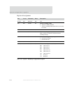
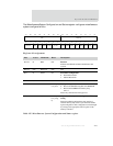
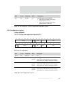
D05 R CS1P HW strap
gpio[49]
Chip select 1 polarity HW strap setting
Status bit indicating the hardware strap setting of
external memory chip select 1 polarity. The polarity can
be changed by writing to the appropriate control
registers in the memory controller.
D04 R Reserved N/A N/A
D03 R/W ENDM HW strap
gpio[44]
Endian mode
0 Little endian mode
1 Big endian mode
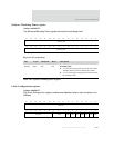
D02 R/W MBAR 0x0 Misaligned bus address response mode
0 Allow misaligned bus addresses
1 Generate an error response when a misaligned bus
address is found; that is, when
haddr bits 1 or 0 are
not level 0.
D01 N/A Reserved N/A N/A
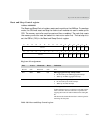
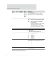
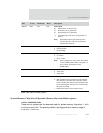
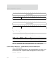
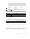
Bits Access Mnemonic Reset Description
Table 187: Miscellaneous System Configuration and Status register