www.digiembedded.com
647
Serial Control Module: SPI
FIFO management
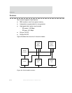
Data flow between a serial controller and memory occurs through the FIFO blocks
within each serial controller module. Each serial controller provides both a 32-byte
transmit FIFO and a 32-byte receive FIFO. Each FIFO is arranged as eight lines of four
bytes to facilitate data transfer across BBus. Both the transmit and receive FIFOs are
accessed using the Serial Channel B/A/C/D FIFO registers.
Transmit FIFO interface
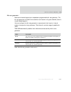
The processor can write either 1, 2, 3, or 4 bytes at a time to the transmit FIFO. The
number of bytes written is controlled by the data size defined by the
HSIZE field on
the AMBA AHB bus.
When the system is configured to operate in big endian mode, the most
significant bytes in the word written to the FIFO are transmitted first. For
example, the long word
0x11223344 results in the character 0x11 being
transmitted first, and
0x44 being transmitted last.
When the system is configured to operate in little endian mode, the least
significant bytes in the word written to the FIFO are transmitted first. For
example, the long word 0x11223344 results in the character 0x44 being
transmitted first, and
0x11 being transmitted last.
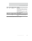
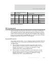
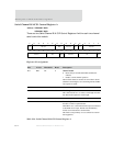
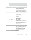
Serial channel B/A/C/D bit rate
register settings Mode functionality
SPI
mode SPCPOL TXCINV RXCINV
SPI CLK
Idle
SPI DATA_IN
capture edge
SPI DATA-OUT
drive edge
0100LowRising Falling
1011HighFalling Rising
2111LowFalling Rising
3000HighRising Falling
Table 381: SPI mode definitions


