DMA Control and Status registers
514
NS9750 Hardware Reference
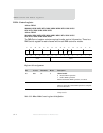
DMA Control register
Address: DMA1
9000 0010 / 0030 / 0050 / 0070 / 0090 / 00B0 / 00D0 / 00F0 / 0110 / 0130 /
0150 / 0170 / 0190 / 01B0 / 01D0 / 01F0
Address: DMA2
9011 0010 / 0030 / 0050 / 0070 / 0090 / 00B0 / 00D0 / 00F0 / 0110 / 0130 /
0150 / 0170 / 0190 / 01B0 / 01D0 / 01F0
The DMA Control register contains required transfer control information. There is a
DMA Control register for each channel within each DMA controller module.
Register bit assignment
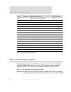
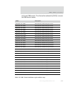
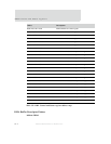
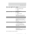
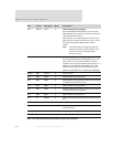
Bits Access Mnemonic Reset Description
D31 R/W CE 0 Channel enable
0 Disables DMA operations
1 Enables DMA operations
Enables and disables DMA operations, as wanted.
D30 R/W CA 0 Channel abort
When set, causes the current DMA operation to complete
and closes the buffer.
D29:28 R/W BB 0 Bus bandwidth
Always set to 0.
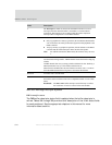
Table 313: BBus DMA Control register bit definition
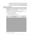
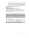
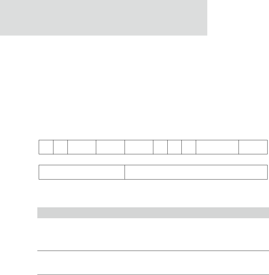
13121110987654321015 14
STATE
31 29 28 27 26 25 24 23 22 21 20 19 18 17 1630
BB Not usedREQ BDRCE CA SIZE
INDEX
MODE BTE
SINC_N


