FIFO management
648
NS9750 Hardware Reference
Processor interrupts vs. DMA
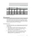
The transmit FIFO can be filled using processor interrupts or the DMA controller.
Using processor interrupts
The processor can write one long word (4 bytes) of data to the transmit FIFO when
the TRDY field in Serial Channel B/A/C/D Status Register A (see "Serial Channel B/A/
C/D Status Register A," beginning on page 657) is active high. If the THALF field in
Serial Channel B/A/C/D Status Register A is active high, the processor can write four
long words (16 bytes) of data to the transmit FIFO. To facilitate an interrupt when
either the TRDY or THALF status bits are active, the processor can set one or both of
the corresponding interrupt enables (in "Serial Channel B/A/C/D Control Register A,"
beginning on page 652).
Using the DMA controller
When using the DMA controller, the processor need not interface with any of the
serial port registers for data flow; rather, the processor must interface with the DMA
channel registers and DMA buffer descriptor block. To facilitate the use of transmit
DMA, the EXTDMA field in Serial Channel B/A/C/D Control Register A must be set
active high. When the ETXDMA field is set active high, disable the serial transmitter
interrupts.
Receive FIFO interface
The receive FIFO presents up to four bytes of data at a time to the processor
interface. The number of valid bytes found in the next read of the FIFO is defined by
the information in the RXFDB field (in "Serial Channel B/A/C/D Status Register A" on
page 657).
When the system is configured to operate in big endian mode, the most
significant bytes in the word written to the FIFO are read first. For
example, the long word
0x11223344 results in the character 0x11 being read
first, and
0x44 being read last.
When the system is configured to operate in little endian mode, the least
significant bytes in the word written to the FIFO are read first. For
example, the long word
0x11223344 results in the character 0x44 being read
first, and
0x11 being read last.


