


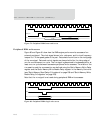

SPI-EEPROM boot logic
486
NS9750 Hardware Reference
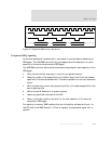
Memory Controller configuration
Note:
See your ARM documentation for complete information about the memory
controller.
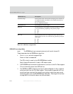
The memory controller exits the reset state in non-operational mode. This requires
the SPI-EEPROM boot logic to configure the memory controller as well as the external
SDRAM before any memory access.
Important:
The information required to configure the memory controller and the
external SDRAM must be stored in a configuration header in the SPI-
EEPROM in a contiguous block starting at address zero. Each entry in the
header, with the exception of the pad entry, must be 4 bytes in length.
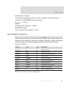
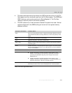
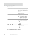
The size of the configuration header varies from 128 bytes to 130 bytes, due to the
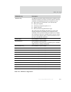
variable length nature of the SPI-EEPROM read command. Table 293 shows the order
and contents of the configuration header.
EEPROM entry Description
Pad entry Variable length entry that ranges from 0 bytes to 2 bytes in length.
The field length is computed by subtracting the length of the read
command (including the address field) from 4.
Example
A 256 Kb EEPROM requires a 1-byte read command followed by a
2-byte address, resulting in a pad entry length of 1:
4-(1+2) = 1
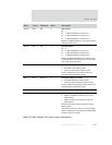
Num words Total number of words to fetch from the SPI-EEPROM. The total
must include the 32-word header plus the initial discarded word.
# words = ((S
1
+ S
2
) / 4) + 1)
S
1
= Code image size in bytes
S
2
= header = 128 bytes
Table 293: ARM boot configuration