Serial port control and status registers
614
NS9750 Hardware Reference
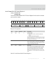
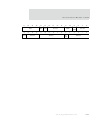
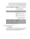
Serial Channel B/A/C/D Control Register B
Address: 9020 0004 / 0044
9030 0004 / 0044
There are two Serial Channel B/A/C/D Control Registers B within each two-channel
serial controller module.
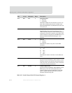
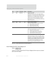
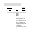
D08 R/W ERXDMA 0 Enable receive DMA
Enables the receiver to interact with a DMA channel.
The channel is configured to operate in DMA mode when
ERXDMA is set to 1. In DMA mode, the DMA controller
empties the receive data FIFO and delivers the data to
memory. The receive status information from Status
Registers B and C are moved automatically to the receive
DMA buffer descriptor.
This bit is cleared to pause the receiver.
D07:05 R/W RIC 000 Receiver interrupt condition
Defines the interrupt enables for a receiver interrupt:
[7] Change in DCD interrupt enable
[6] Change in RI interrupt enable
[5] Change in DSR interrupt enable
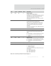
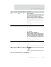
D04:01 R/W TIC 0x0 Transmitter interrupt condition
Defines the interrupt enables for a transmitter interrupt:
[4] Change in CTS interrupt enable
[3] Transmit register empty interrupt enable
[2] Transmit FIFO half-empty interrupt enable
[1] Transmit buffer closed interrupt enable
D00 R/W ETXDMA 0 Enable transmit DMA
Enables the transmitter to interact with a DMA channel.
The channel is configured to operate in DMA mode when
ETXDMA is set to 1. In DMA mode, the DMA controller
loads the transmit data FIFO from memory. The transmit
status information from Status Register C is moved
automatically to the transmit DMA buffer descriptor.
This bit is cleared to pause the transmitter.
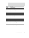
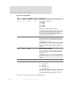
Bits Access Mnemonic Reset Description
Table 367: Serial Channel B/A/C/D Control Register A


