www.digiembedded.com
485
BBus Bridge
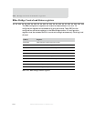
Calculation and example
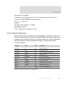
This equation calculates the amount of time, in seconds, required to copy the
contents of the SPI-EEPROM to external memory:
Time = (1 / freq) * EEPROM
SIZE
Example
SPI master clock frequency = 1.5 MHz
SPI-EEPROM = 256 Kb
Time for operation to complete = 175 ms
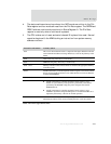
Serial Channel B configuration
When exiting the power-on reset state, serial channel B is in SPI master mode, which
facilitates communication with the external SPI-EEPROM. When the copy operation is
complete, serial channel B is returned to its default reset state. The next table shows
which configuration fields are updated by hardware, allowing the SPI master
interface to operate.
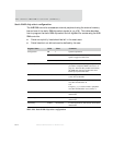
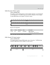
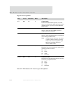
Register Field Value Description
Control A CE 0x1 Enable the channel
Control A WLS 0x3 8 data bits per word
Control B CSPOL 0x0 Chip select polarity to active low
Control B MODE 0x2 SPI master mode
Control B BITORDR 0x1 Bit order to MSB first
Bit rate EBIT 0x1 Enable the bit rate generator
Bit rate TMODE 0x1 Synchronous timing
Bit rate CLKMUX 0x1 Select BBus clock as reference
Bit rate TXCINV 0x1 Transmit clock inverted
Bit rate N 0x00F Create ~1.5 MHz SPI clock
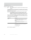
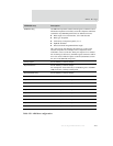
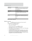
Table 292: SPI master mode boot configuration


