


www.digiembedded.com
335
Ethernet Communication Module
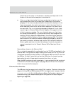
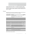
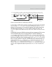
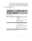
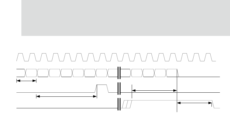
Figure 68: External Ethernet CAM filtering for MII PHY
In this example, the MII receive interface is transferring a frame whose first 6 nibbles
have the values 1, 2, 3, 4, 5, and 6. The external CAM hardware uses the
CAM_REQ
signal to find the alignment for the destination address. After lookup is performed,
the CAM hardware can assert the CAM_REJECT signal to discard the frame. The
CAM_REJECT signal must be asserted no later than the 4
th
nibble from the end of the
frame.
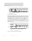
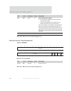
For RMII PHYs, the external CAM filtering logic is different, because the PHY interface
is 2 bits at 50 MHz rather than the 4 bits at 25 MHz for a MII PHY. Because the
CAM_REQ signal is generated from the 25 MHz clock, it cannot be used reliably with
external 50 MHz logic to identify the start of a new frame. The external logic instead
should use the RMII PHY receive interface signals (that is,
RXD[1:0], CRS_DV) to find the
start of a frame, as shown in Figure 69. The RMII specification defines the start of a
frame preamble when CRS_DV is high and RXD[1:0] transitions from 00 to 01. Per the
specification,
CRS_DV is asserted asynchronously to REF_CLK, to indicate the CRS
function. When RXD[1:0] transitions from 00, however, CRS_DV performs the data valid
function, and is negated and asserted synchronous to
REF_CLK until the end of the
frame.
5D
2
14365789
A
BC
Preamble/
SFD
Reject Setup to
End of Packet
(4 RXCLKs)
Reject Hold From
End of Packet
(3 RXCLKs)
5 RXCLKs
RX_CLK
RXD[3:0]
CAM_REQ
CAM_REJECT