Serial port control and status registers
612
NS9750 Hardware Reference
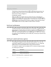
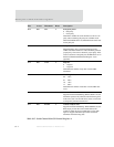
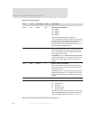
D28 R/W EPS 0 Even parity select
0 Odd parity
1 Even parity
Determines whether the serial channel uses odd or even
parity when calculating the parity bit in UART mode.
When the STICKP field is set, EPS defines the static state
for the parity bit.
D27 R/W PE 0 Parity enable
Enables/disables parity generation/checking for the
UART transmitter and receiver. The transmitter generates
proper parity. The receiver checks for proper parity. If the
receiver encounters a bad parity bit, the RPE field is set in
the Serial Channel B/A/C/D Status Register A (see
page 620).
D26 R/W STOP 0 Stop bits
0 1 stop bit
1 2 stop bits
Determines the number of stop bits in each UART
transmitter.
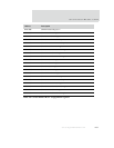
D25:24 R/W WLS 00 Word length select
00 5 bits
01 6 bits
10 7 bits
11 8 bits
Determines the number of data bits in each UART data
word.
D23 R/W CTSTX 0 Activate clear to send
Supports hardware handshaking. When CTSTX is set, the
transmitter operates only when the external CTS signal is
in the active state. An external device, then, can use CTS
to temporarily stall data transmission.
D22 R/W RTSRX 0 Activate ready to send
Supports hardware handshaking. When RTSRX is set, the
RTS output provides the receiver FIFO almost-full
condition. When the receiver FIFO backs up, the RTS
signal is dropped. The RTS output stalls an external
transmitter from delivering data.
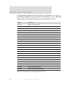
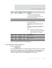
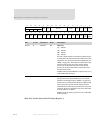
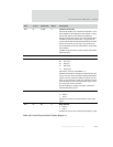
Bits Access Mnemonic Reset Description
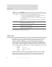
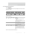
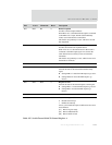
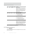
Table 367: Serial Channel B/A/C/D Control Register A


