www.digiembedded.com
553
I2C Master/Slave Interface
Interrupt Codes
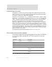
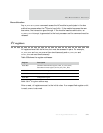
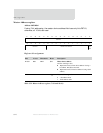
Interrupts are signaled in the irq_code field in the STATUS_REG, by providing the
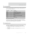
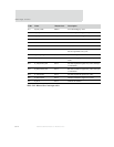
appropriate interrupt code (see Table 342: "Master/slave interrupt codes" on page
553). The ARM CPU waits for an interrupt by polling the
STATUS_REG or checking the irq
signal. An interrupt is cleared by reading the
STATUS_REG, which also forces the irq
signal down (minimum one cycle if another interrupt is stored).
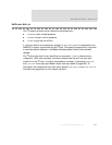
Note:
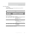
RX_DATA_REG contains only a received byte if it is accessed after a RX_DATA
master or slave interrupt is signaled. At all other times, the internal
master or slave shift register is accessed with
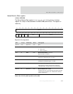
RX_DATA_REG (see "Status
Receive Data register" on page 549).
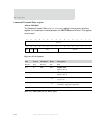
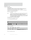
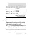
D14 R/W TMDE 1 Timing characteristics of serial data and serial clock
0 Standard mode
1 Fast mode
D13 R/W VSCD 1 Virtual system clock divider for master and slave
Must be set to 0.
D12:09 R/W SFW F
hex
Spike filter width
A default value of 1 is recommended. Available values are
0–15.
D08:00 R/W CLREF 00
hex
clk_ref[9:1]
The I2C clock on port iic_scl_out is generated by the
system clock divided by the 10-bit value of clk_ref.
Note: The LSB of clk_ref cannot be programmed,
and is set to 0 internally. The programmed
value of clk_ref[9:1] must be greater than 3.
Bits Access Mnemonic Reset Description
Table 341: Configuration register
Code Name Master/slave Description
0
hex
NO_IRQ N/A No interrupt active
1
hex
M_ARBIT_LOST Master Arbitration lost; the transfer has to be repeated
Table 342: Master/slave interrupt codes


