Serial port control and status registers
622
NS9750 Hardware Reference
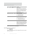
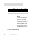
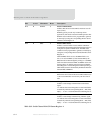
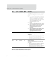
D10 R RHALF 0 Receive FIFO half full
Indicates that the receive data FIFO contains at least 20
bytes (5 lines).
RHALF typically is used only in interrupt-driven
applications; this field is not used for DMA operation. The
RHALF status condition can be programmed to generate
an interrupt by setting the corresponding IE bit in Serial
Channel Control Register A.
D09 R RBC 0 Receive buffer closed
Indicates a receive buffer closed condition. Hardware
automatically acknowledges this field when the receiver is
configured to operate in DMA mode. The RBC status
condition can be programmed to generate an interrupt by
setting the corresponding IE bit in Serial Channel Control
Register A.
While the RBC field is active, the RRDY field is not
active. To activate RRDY (to read the data FIFO), the
RBC bit must be acknowledged by writing a 1 to the RBC
field. This interlock between RBC and RRDY allows the
firmware driver to read the status bits in Serial Channel
Status Register A or Status Register B. When operating in
DMA mode, hardware automatically handles the interlock
between RBC and RRDY.
D08 R RFS 0 Receive FIFO status
Reflects the current state of the receive FIFO. When set to
1, the receive FIFO has room for only one more line of
data.
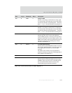
D07 RW1TC DCDI 0 Change in DCD
Indicates a state change in the EIA data carrier detect
signal.
A 1 indicates that a state change has occurred. This field is
asserted only when the corresponding IE bit — RIC field,
D[07] — is set to 1 in Serial Channel Control Register A.
D06 R RII 0 Change in RI
Indicates a state change in the EIA ring indicator signal.
A 1 indicates that a state change has occurred. This field is
asserted only when the corresponding IE bit — RIC field,
D[06] — is set to 1 in Serial Channel Control Register A.
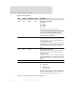
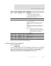
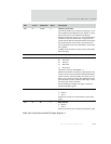
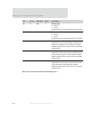
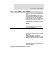
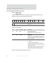
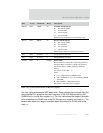
Bits Access Mnemonic Reset Description
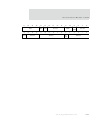
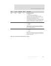
Table 369: Serial Channel B/A/C/D Status Register A


