www.digiembedded.com
823
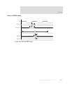
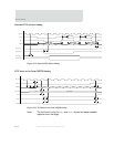
Timing
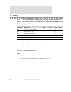
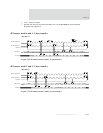
Notes:
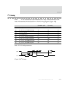
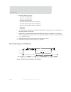
1 CLCDCLK is selected from 5 possible sources:
— lcdclk/2 (lcdclk is an external oscillator)
— AHB clock
— AHB clock/2
— AHB clock/4
— AHB clock/8
See the LCD Controller chapter for acceptable clock frequencies for the different display configurations.
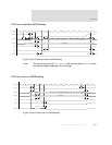
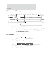
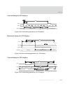
2 The polarity of CLLP, CLFP, CLCP, and CLAC can be inverted using control fields in the LCDTiming1 register.
3 The CPL field in the LCDTiming2 register must also be programmed to T5-1.
4 The PPL field in the LCDTiming0 register must also be programmed correctly.
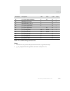
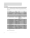
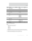
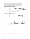
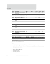
L18 CLCP to data/control
(see notes 7 and 8)
-1.0 (min)
+1.5 (max)
ns
L19 CLCP high (see notes 8, 9) 50%±0.5ns ns
L20 CLCP low (see notes 8, 9) 50%±0.5ns ns
L21 TFT VSYNC active to HSYNC
active (see note 8)
-0.1ns (min)
+0.1ns (max)
ns
L22 TFT VSYNC active to HSYNC
inactive
LCDTiming0 HSW CLCP periods
L23 STN VSYNC active to HSYNC
inactive
LCDTiming0 STN color: 14+HSW+HFP
STN Mono8:
6+HSW+HFP
STN Mono4:
10+HSW+HFP
CLCP periods
L24 STN HSYNC inactive to
VSYNC inactive
LCDTiming0 HBP+1 CLCP periods
L25 STN VSYNC inactive to
HSYNC active
LCDTiming0 STN color: HFP+13
STN Mono8: HFP+15
STN Mono4: HFP+9
CLCP periods
L26 CLCP period 12.5ns (min) ns
Parm Description Register Value Units
Table 474: LCD timing parameters


