www.digiembedded.com
573
LCD Controller
RAM palette
The palette RAM is a 256 x 16 bit dual port RAM, physically structured as 128 x 32 bit.
This allows two entries to be written into the palette from a single word write access.
The least significant bit of the serialized pixel data selects between upper and lower
halves of the palette RAM. The half selected depends on the byte-ordering mode. In
little endian mode, setting the least significant bit selects the upper half of the
palette; in big endian mode, setting the least significant bit selects the lower half.
Because WinCE byte ordering is little endian, setting the least significant byte results
in selection of the upper half of the palette.
Pixel data values can be written and verified using the slave interface.
The palette RAM has independent controls and addresses for each port.
Port1 is used as a read/write port, and is connected to the AHB slave
interface. The palette entries can be written and verified through this port.
Port2 is used as a read-only port, and is connected to the unpacker and
grayscaler.
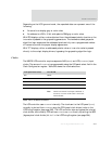
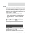
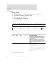
Table 344 shows the bit representation of each word in the palette.
For mono STN, only the red palette field bits (4:1) are used. In STN color mode,
however, the green and blue [4:1] are also used.
Red and blue pixel data can be swapped to support BGR data format using the
appropriate control register bit.
Bit Name Description
31 I Intensity/unused
30:26 B[4:0] Blue palette data
25:20 G[4:0] Green palette data
19:16 R[4:0] Red palette data
15 I Intensity/unused
14:10 B[4:0] Blue palette data
09:05 G[4:0] Green palette data
04:00 R[4:0] Red palette data
Table 344: Palette data storage


