System configuration registers
302
NS9750 Hardware Reference
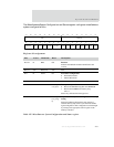
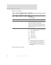
Register bit assignment
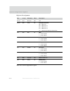
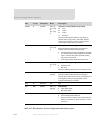
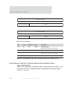
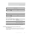
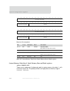
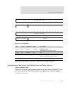
Bits Access Mnemonic Reset Description
31:16 N/A Reserved N/A N/A
D15 R/W TEN 0x0 Timer enable
0 Timer is disabled
1 Timer is enabled
D14:10 N/A Reserved N/A N/A
D09 R/W INTC 0x0 Interrupt clear
Clears the timer interrupt. System software must write a 1,
then a 0 to this location to clear the interrupt.
If the timer is programmed to halt on terminal count (that
is, REN is clear), the software must disable the timer by
setting TEN to 0 before clearing the interrupt by writing a
1 and then a 0 to INTC.
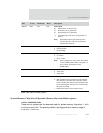
D08:06 R/W TLCS 0x0 Timer clock select
000 CPU clock (must be used if this is the high word
of two concatenated timers)
001 CPU clock / 2
010 CPU clock / 4
011 CPU clock / 8
100 CPU clock / 16
101 CPU clock / 32
110 CPU clock / 64
111 External pulse event
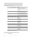
Notes:
Counting external pulse events, the frequency must
be less than one-half the CPU clock frequency.
For TLCS settings 000 – 110, the terminal count can
be output using GPIO. The terminal count pulse
width will be one CPU clock cycle, regardless of the
TLCS setting.
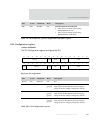
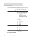
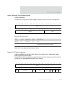
Table 190: Timer Control register


