UART mode
604
NS9750 Hardware Reference
UART mode
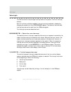
Many applications require a simple mechanism for sending low-speed information
between two pieces of equipment. The universal asynchronous/synchronous
receiver/transmitter (UART) protocol is the de facto standard for simple serial
communications. The protocol does not require sending clock information between
the two parties; rather, the UART receiver uses an over-sampling technique to find
the bit-level framing of the UART protocol. The UART framing structure is as follows:
Start bit: 0
Data bits: 5, 6, 7, or 8
Parity: Odd, even, or no parity
Stop bits: 1 or 2
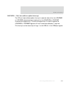
Because the transmitter and receiver operate asynchronously, there is no need to
connect transmit and receive clocks between them. Instead, the receiver over-
samples the receive data stream by a factor of 16. During synchronization, the
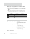
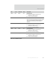
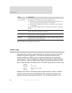
Name Description
X1_SYS_OSC/M The frequency of the external crystal oscillator divided by 2 or 4.
The divisor is 2 when the PLLND field in the PLL Configuration register is at
least 0x13, producing a nominal frequency of 14.7456 MHz.
The divisor is 4 when PLLND is less than 0x13, producing a nominal frequency
of 7.3728 MHz.
See the System Control Module chapter for information about the PLL Configuration
register.
BCLK The clock source for all peripherals that are attached to the BBus. The frequency of
BCLK is the AHB clock frequency divided by 2.
ExtRxClk External receive clock on GPIO pins gpio[6], gpio[14], gpio[22], and gpio[26] for
serial ports B, A, C, and D, respectively.
ExtTxClk External transmit clock on GPIO pins gpio[7], gpio[15], gpio[23], and gpio[27] for
serial ports B, A, C, and D, respectively.
Table 364: Bit-rate generation clock sources


