


www.digiembedded.com
475
BBus Bridge
When the current descriptor is retired, the next descriptor is accessed from a circular
buffer.
Each DMA buffer descriptor requires four 32-bit words to describe a transfer. Circular
buffers of 1024 bytes contain multiple buffer descriptors. The first buffer descriptor
address is provided by the DMA channel’s Buffer Descriptor Pointer register.
Subsequent buffer descriptors are found adjacent to the first descriptor. The final
buffer descriptor is defined with its W bit set. When the DMA channel encounters the
W bit, the channel wraps around to the first descriptor.
Each DMA channel can address a maximum of 64 buffer descriptors, each consisting of
16 bytes. Configuring the DMA channel for more than the maximum number of buffer
descriptors results in unpredictable behavior.
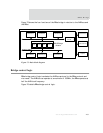
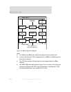
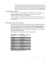
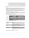
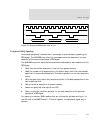
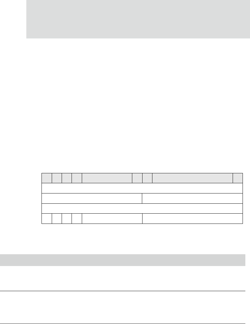
Figure 77 shows the DMA buffer descriptor. Table 289 describes each section.
Figure 77: BBus bridge DMA buffer descriptor
Field/Section Description
Source address Identifies the starting location of the source data. The source address can
be aligned to any byte boundary. Optimum performance results when the
source address is aligned on a word boundary
Buffer length Indicates the number of bytes to move between the source and the
destination.
After completing the transfer, the DMA controller updates this field with
the actual number of bytes moved.
Destination address Identifies the beginning of the location to which the source data will be
moved. The destination address can be aligned to any byte boundary.
Optimum performance results when the destination address is aligned on a
word boundary.
Table 289: BBus bridge DMA buffer descriptor definition
Destination Address
Buffer Length
Status
Source Address
OFFSET + 0
OFFSET + 4
OFFSET + 8
OFFSET + C
FILW Reserved
31 30 29 28 16 15 0
Reserved