DMA Control and Status registers
518
NS9750 Hardware Reference
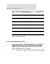
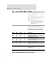
D28 RW1TC CAIP 0 Channel abort interrupt pending
Set when the DMA channel finds the CA bit set in the
DMA Channel Control register. An interrupt is generated
when the CAIE (D21) bit is set.
When CAIP Is set, the DMA channel retires the current
buffer descriptor and stops until firmware writes a 1 to the
CE bit (in the appropriate DMA Channel Control
register).
Note: The CA bit must be cleared, using firmware,
before the CE field is written. Failure to reset
the CA bit causes the subsequent buffer
descriptor to abort.
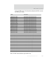
D27 R/W PCIP 0 Premature complete interrupt pending
Set when the DMA channel, configured for fly-by write
mode, receives an end-of-transfer indicator from the
peripheral while processing a DMA buffer descriptor. An
interrupt is generated if the PCIE (D20) bit is set. The
DMA channel continues processing buffer descriptors.
NCIP is set when PCIP is set, for backward compatibility.
D26:25 R/W Unused 0 Always set to 0.
D24 R/W NCIE 0 Enable NCIP interrupt generation.
D23 R/W ECIE 0 Enable ECIP interrupt generation. This bit always should
be enabled during normal operation.
D22 R/W NRIE 0 Enable NRIP interrupt generation.
D21 R/W CAIE 0 Enable CAIP interrupt generation. This bit always should
be enabled during normal operation.
D20 R/W PCIE 0 Enable PCIP interrupt generation.
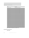
D19 R WRAP 0 Debug field, indicating the last descriptor in the descriptor
list.
D18 R IDONE 0 Debug field, indicating interrupt on done.
D17 R LAST 0 Debug field, indicating the last buffer descriptor in the
current data frame.
D16 R FULL 0 Debug field, indicating the buffer is full.
D15:00 R BLEN 0x000 Debug field, indicating the remaining byte transfer count.
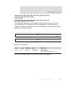
Bits Access Mnemonic Reset Description
Table 314: DMA Status/Interrupt Enable register bit definition


